Building decorative sheet cutting machine convenient to adjust

A technology for plate cutting machinery and architectural decoration, applied in sawing equipment, manufacturing tools, wood processing appliances, etc., can solve the problems of unfavorable equipment use, inconvenient movement, limited cutting range, etc., to achieve high work stability and improve applicability , good cutting effect

Inactive Publication Date: 2018-07-27
佛山市博蓄科技有限公司
View PDF8 Cites 0 Cited by
  • Summary
  • Abstract
  • Description
  • Claims
  • Application Information

AI Technical Summary

Problems solved by technology

The direction of the cutting machine of the existing building decorative board cutting machine is consistent with the cutting surface of the cutting base. When the diameter of the wood is too large, the wood cannot be cut off as a whole, and the wood must be turned to cut gradually, resulting in poor cutting effect and limited cutting range. , the applicability is low, and at the same time, the equipment is large in size and it is inconvenient to move. Some equipment equipped with pulleys has low stability during work, and there is no good shock absorption device, which cannot be used for shock absorption and noise reduction, which is not conducive to the use of equipment.

Method used


Image

  • Building decorative sheet cutting machine convenient to adjust
  • Building decorative sheet cutting machine convenient to adjust
  • Building decorative sheet cutting machine convenient to adjust

Examples


Embodiment Construction

[0022] The preferred embodiments of the present invention will be described below in conjunction with the accompanying drawings. It should be understood that the preferred embodiments described here are only used to illustrate and explain the present invention, and are not intended to limit the present invention.

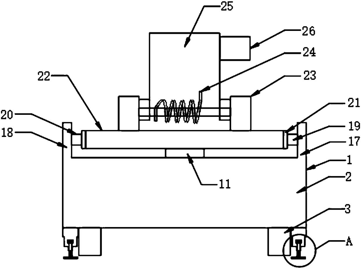
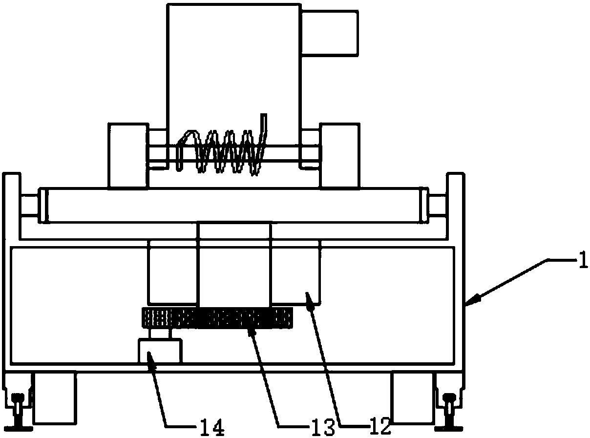
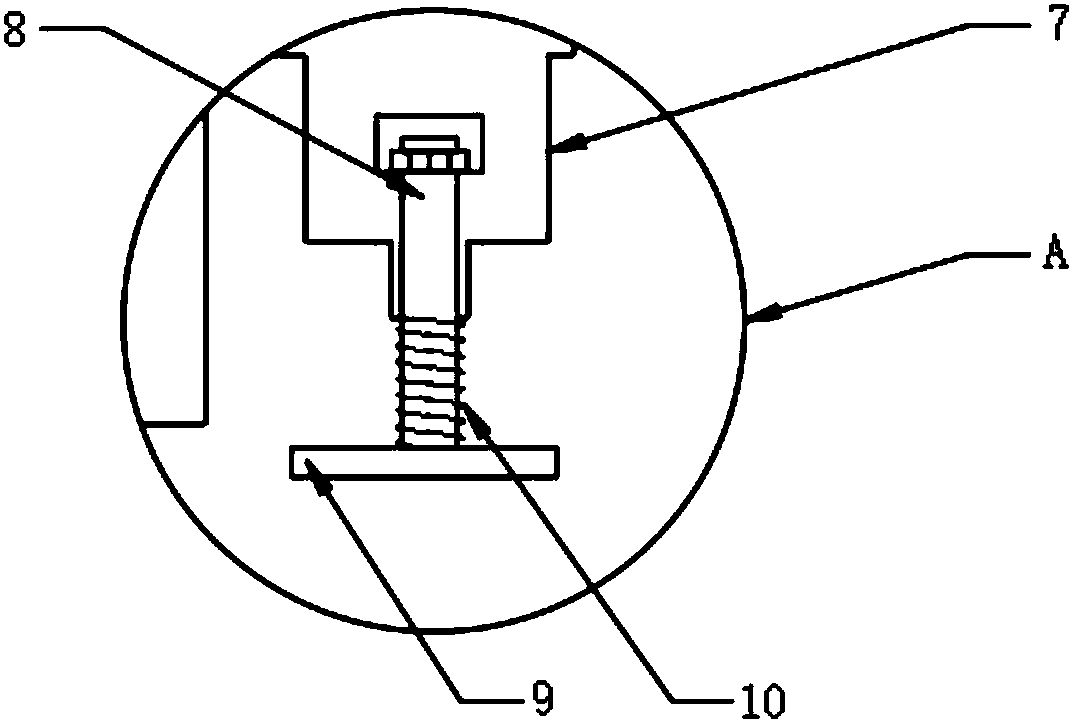
[0023] see Figure 1-6 , the present invention provides a technical solution: a cutting machine for building decorative panels that is easy to adjust, including a cutting machine body 1, a base 2, a housing 3, a groove 4, a first hydraulic cylinder 5, a pulley 6, a connecting block 7, The first support rod 8, the support plate 9, the damping spring 10, the rotating rod 11, the bearing 12, the driven gear 13, the servo motor 14, the motor shaft 15, the driving gear 16, the first support 17, the second support 18, the first Second hydraulic cylinder 19, third hydraulic cylinder 20, fastening block 21, support seat 22, second support rod 23, return force spring 24, mec...


PUM


Abstract

The invention discloses a building decorative sheet cutting machine convenient to adjust. The building decorative sheet cutting machine convenient to adjust comprises a cutting machine body. A grooveis internally provided with a first hydraulic cylinder. One end of the first hydraulic cylinder is provided with sliding wheels. The outer side of a shell is connected with a connection block in a welded manner. The connection block is internally provided with a first supporting rod in an insertion manner. The bottom end of the first supporting rod is provided with a supporting disk in a welded manner. The part between the bottom of the first supporting rod and the supporting disk is sleeved with a damping spring. The middle of the interior of the base is provided with a rotating rod in an insertion manner. One end of the rotating rod is provided with a driven gear. The bottom end of the interior of the cutting machine body is provided with a servo motor. The top end of the servo motor isprovided with a motor shaft. The top end of the motor shaft is provided with a drive gear. By means of the building decorative sheet cutting machine convenient to adjust, a timber can be integrally cut at a time, the cutting effect is good, the applicability of the equipment is improved, meanwhile, moving is facilitated, the working stability is high, and certain damping and noise reducing functions are achieved.

Description

technical field [0001] The invention relates to a cutting machine, in particular to a building decoration board cutting machine which is easy to adjust. Background technique [0002] With the development of the modern mechanical processing industry, the requirements for cutting quality and precision are constantly improving, and the requirements for improving production efficiency, reducing production costs, and highly intelligent automatic cutting functions are also increasing. Cutting machines are used in metal and non-metallic The metal industry, generally speaking, the non-metal industry is more detailed, such as stone cutting machines for cutting stone, water cutting machines, sawtooth cutting machines, cutting cloth and plastics, laser cutting machines for chemical fiber products, and blade cutting machines. The direction of the cutting machine of the existing building decorative board cutting machine is consistent with the cutting surface of the cutting base. When the...

Claims


Application Information

Patent Timeline
IPC IPC(8): B27B5/02B27B5/29B27B5/38
CPCB27B5/02B27B5/29B27B5/38
Inventor 傅飞艳
Owner 佛山市博蓄科技有限公司
Why Eureka
Try Eureka