Interface method of EMU depot (office) control centralized system and signal system

A signal system and centralized system technology, which is applied in the interface field of the centralized system and the signal system controlled by the EMU, can solve the problems of full utilization of unfavorable resources, repeated equipment investment, idle control terminals of CTC, etc., so as to improve the working efficiency of equipment, The effect of reducing the data transmission process and reducing the maintenance workload

Active Publication Date: 2018-07-27
CHINA RAILWAY SIYUAN SURVEY & DESIGN GRP
View PDF4 Cites 4 Cited by
  • Summary
  • Abstract
  • Description
  • Claims
  • Application Information

AI Technical Summary

Problems solved by technology

This processing method increases the workload of the CTC system and increases the coupling between the CTC and CCS systems, which is not conducive to the modular design of the system; there is no clear demarcation between the working modes of CTC "decentralized self-discipline" and CCS "centralized control". Determined by the management system
[0012] (2) CTC and CCS system control terminals have not realized mutual card
[0013] From the technical requirements of CTC and CCS, both CTC and CCS switch the control mode through the interlocking system to distinguish whether the system is in the "very station control" mode. CTC and CCS have not realized the switching and interlocking of different control modes. Both CTC and CCS system equipment can be used when it is not in the "very station control" mode. Improper use will cause failure or error to the system
[0014] (3) The control terminal of CTC is idle
On the one hand, repeated investment in equipment is not

Method used


Image

  • Interface method of EMU depot (office) control centralized system and signal system
  • Interface method of EMU depot (office) control centralized system and signal system
  • Interface method of EMU depot (office) control centralized system and signal system

Examples


Embodiment Construction

[0035] In order to make the purpose, technical solutions and advantages of the embodiments of the present invention clearer, the technical solutions in the embodiments of the present invention will be clearly described below in conjunction with the accompanying drawings in the embodiments of the present invention. Obviously, the described embodiments are the Some, but not all, embodiments are invented. Based on the embodiments of the present invention, all other embodiments obtained by persons of ordinary skill in the art without making creative efforts belong to the protection scope of the present invention.

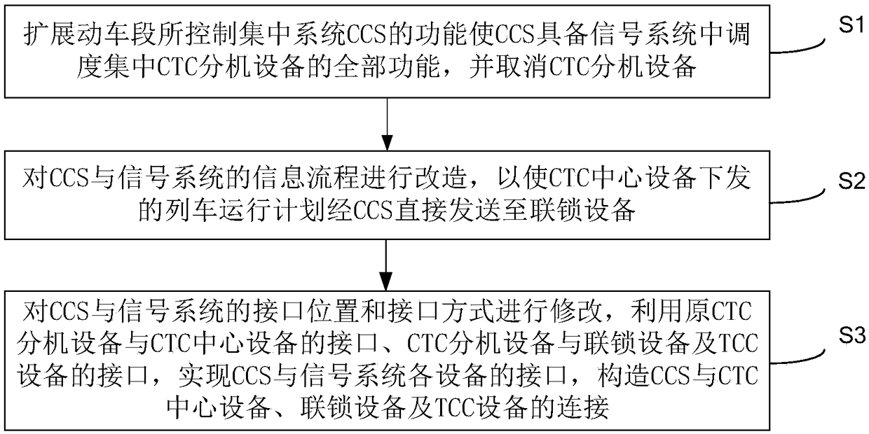
[0036] image 3 A schematic flow chart of the interface method between the central control system and the signal system of the bullet train depot provided by the embodiment of the present invention, as shown in image 3 As shown, including: S1, expanding the functions of the centralized control system CCS of the EMU to enable CCS to have all the functions of the dispat...


PUM


Abstract

The invention provides an interface method of an EMU depot (office) control centralized system and a signal system. The method includes the steps of S1, expanding the functions of the EMU depot (office) control centralized system (CCS) to allow the CCS to have all the functions of centralized traffic control (CTC) extension equipment in the signal system, and omitting the CTC extension equipment;S2, transforming the information flow of the CCS and the signal system to allow the a train operation plane issued by CTC central equipment to be directly transmitted to interlocking equipment throughthe CCS; S3, modifying the interface position and interface manner of the CCS and the signal system to build connection between the CCS and the CTC central equipment and the connection between the interlocking equipment and a train control center (TCC). By the method, the data transmission flow of train operation plan issuing and execution is simplified, risks generated by the simultaneous operation of the CTC extension equipment and the CCS equipment, equipment idleness is reduced, and the equipment work efficiency of an EMU depot (office) is increased.

Description

technical field [0001] The invention relates to the field of railway signal system interface design, in particular to an interface method between a centralized control system and a signal system of a bullet train depot. Background technique [0002] Traditionally, the high-speed rail signaling system mainly includes centralized dispatching (CTC), interlocking, blocking, train control, and centralized monitoring subsystems. The new centralized control system (CCS) in the bullet train depot completes the automatic control functions related to the signal system, such as the acquisition of train plans and the issuance of train route control commands, through the interface with the signal system. [0003] Among them, for CTC: high-speed railways, including passenger dedicated lines and intercity railways, are generally equipped with centralized dispatching (CTC) systems. It is a kind of railway signal technology equipment that commands and manages trains and shunting operations ...

Claims


Application Information

Patent Timeline
IPC IPC(8): B61L27/04
CPCB61L27/04B61L27/30
Inventor 张敏慧王冬梅易承龙谢静高石先明
Owner CHINA RAILWAY SIYUAN SURVEY & DESIGN GRP
Why Eureka
Try Eureka