
Rear-end rough collimator for neutron scattering

A neutron scattering and collimator technology, which is used in material analysis using neutrons, material analysis using wave/particle radiation, instruments, etc. The effect of improving the signal-to-noise ratio and reducing the effective thickness

Inactive Publication Date: 2018-07-27
INST OF HIGH ENERGY PHYSICS CHINESE ACAD OF SCI +1
View PDF6 Cites 2 Cited by
  • Summary
  • Abstract
  • Description
  • Claims
  • Application Information

AI Technical Summary

Problems solved by technology

[0003] In the prior art, a straight-through neutron collimator is generally used, and it is mostly used at the front end of the sample. The collimator at the rear end of the sample is rarely involved, and the neutron passing section is small, which affects the arrangement of the neutron detector.

Method used


Image

  • Rear-end rough collimator for neutron scattering
  • Rear-end rough collimator for neutron scattering
  • Rear-end rough collimator for neutron scattering

Examples


Embodiment Construction

[0023] The specific implementation manner of this embodiment is described in detail below in conjunction with accompanying drawing of description:

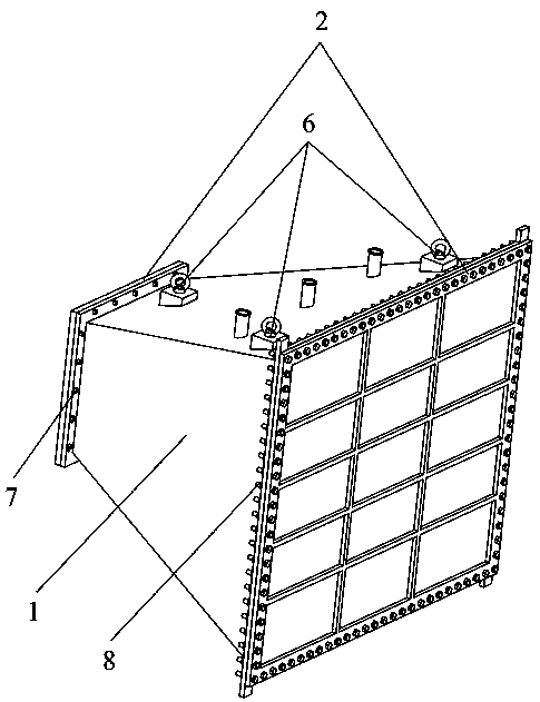
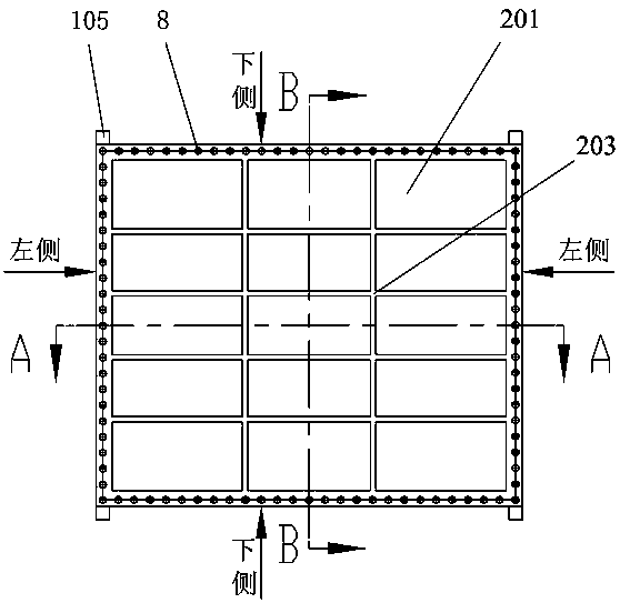
[0024] In this embodiment, the "front end" of the collimator cavity 1 refers to the end face of the collimator cavity 1 that is close to the sample and away from the detector plane, and the "rear end" of the collimator cavity 1 refers to the end surface of the collimator cavity 1 that is far away from the sample. The end surface of the collimator cavity 1 close to the detector plane; the upper, lower, left, and right respectively refer to the upper side and lower side of the collimator cavity 1 with the rear end surface of the collimator cavity 1 as the main view. , left side and right side.

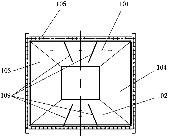
[0025] Such as Figure 1-6 As shown, a rear-end rough collimator for neutron scattering mainly includes a collimator cavity 1, a sealing plate 2, a boron carbide shielding block 3 and a boron carbide ceramic insert sheet 4, the collimator ...


PUM


Abstract

The invention relates to the field of science and technologies for neutron scattering, in particular to a rear-end rough collimator for neutron scattering. The rear-end rough collimator mainly comprises a collimator cavity, sealing plates, boron carbide shielding blocks and boron carbide ceramic inserting pieces, wherein the collimator cavity is a frustum-shaped hollow cavity with front and rear openings, the boron carbide shielding blocks are mounted on the inner side surface of wall boards of the collimator cavity, the boron carbide ceramic inserting pieces are mounted in the collimator cavity and segment the inside of the cavity into multiple channel spaces, so that the center of the collimator cavity is colinear with the center of a prism light path, and the sealing plates are mountedat the front and rear opening of the collimator cavity respectively. The frustum-shaped cavity defined by the collimator cavity and the boron carbide shielding blocks completely envelops frustum-shaped neutron light paths perpendicularly shot to the plane of a detector after scattering by a sample, and the light shielding phenomenon in the neutron beam direction is avoided; stray neutrons outsidethe collimator cavity can be absorbed, and beam background is reduced; manufacturing and mounting of the collimator cavity is better facilitated.

Description

technical field [0001] The invention relates to the field of neutron scattering science and technology, in particular to a back-end rough collimator for neutron scattering. Background technique [0002] Neutrons have unique advantages such as uncharged, penetrating, magnetic moment, sensitive to light elements, and able to distinguish isotopes and adjacent elements, making neutron scattering technology widely used in physics, chemistry, new energy, life, medicine, materials, It plays an irreplaceable role in scientific research and industrial applications such as engineering and national security. In the neutron scientific research experiment, in order to analyze the information such as the crystal structure and magnetic structure of the sample, several detector arrays need to be installed around the sample to receive the neutrons after the sample is irradiated, and provide technical support for subsequent data acquisition and data analysis . However, the flux of neutrons ...

Claims


Application Information

Patent Timeline
Patent Type & Authority Applications(China)
IPC IPC(8): G01N23/00
CPCG01N23/005
Inventor 何伦华康乐罗平陈洁卢怀乐
Owner INST OF HIGH ENERGY PHYSICS CHINESE ACAD OF SCI
Learn More