Automatic detection system and method for distribution line fault indicator

A fault indicator and automatic detection technology, applied in the direction of instruments, measuring devices, measuring electrical variables, etc., can solve the problems of poor single-phase ground fault identification ability and detection ability, small batch detection number, and low degree of automation.

Pending Publication Date: 2018-07-27
CHINA ELECTRIC POWER RES INST +1
View PDF0 Cites 12 Cited by
  • Summary
  • Abstract
  • Description
  • Claims
  • Application Information

AI Technical Summary

Problems solved by technology

At present, for the detection of various types of distribution line fault indicators, the degree of automation is low. The existing detection systems and methods mainly include RTDS simulation, protection devices, and true type detection systems. However, the use of RTDS simulation tools has poor load capacity. It is easy to be distorted, the number of batch detection is small, and the efficiency is low; the use of protective devices cannot accurately simulate the transient characteristics of ground faults, especially the detection ability of single-phase ground faults in small current grounding systems is poor; the use of primary equipment is directly built The experimental environment covers a large area, has few testing items, poor flexibility and high risk

Method used


Image

  • Automatic detection system and method for distribution line fault indicator
  • Automatic detection system and method for distribution line fault indicator
  • Automatic detection system and method for distribution line fault indicator

Examples


Embodiment Construction

[0083] The technical solutions in the present invention will be clearly and completely described below in conjunction with the accompanying drawings in the present invention.

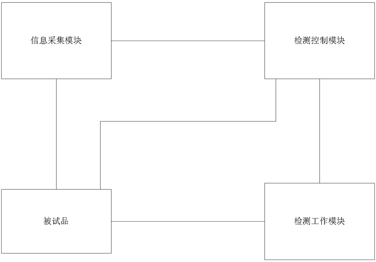
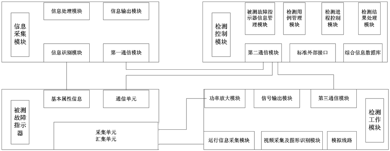
[0084] An automatic detection system for a distribution line fault indicator provided by the present invention, its module schematic diagram is as follows figure 1 As shown, the detection system includes three subsystems: an information collection module, a detection control module and a detection working module.

[0085] An automatic detection system for a distribution line fault indicator, which is characterized in that it includes: an information collection module, a detection control module, and a detection work module.

[0086] The information collection module is used to automatically identify the basic attribute information of the fault indicator under test, and collect the basic attribute information of the distribution line fault indicator to form a standard format and provide it to the detecti...


PUM


Abstract

The invention provides an automatic detection system and method for a distribution line fault indicator. The system is composed of an information acquisition module, a detection control module and a detection work module. The information acquisition module identifies and collects basic attribute information of a detected fault indicator automatically and transmits the collected to the detection control module; the detection control module configures a detection use case, generates a control instruction of the detection work module, and generates a detection report according to the basic attribute information, transmitted by the information acquisition module, of the detected fault indicator; and the detection work module receives the control instruction issued by the detection control module, outputs a detection signal in real time, injects the detection signal into the detected fault indicator automatically, and transmits operation information and response information of a distribution line fault indicator to the detection control module automatically according to a detection result. Therefore, batched detection of fault indicators is realized; the item is detected comprehensively; and the detection efficiency and accuracy are improved.

Description

technical field [0001] The invention relates to the detection of a distribution line fault indicator, in particular to an automatic detection system and method for a distribution line fault indicator. Background technique [0002] In the distribution network system, there are many branches and complex operation conditions. When a short circuit or ground fault occurs, it is difficult to determine the fault section (location), which brings great difficulties to the maintenance work. The distribution line fault indicator is a device installed on the distribution line to monitor line operating parameters, detect and indicate various short circuits and ground faults, and send monitoring information and fault detection data to the main power distribution station. When a line fault occurs, the fault section is determined in time, which greatly shortens the time for finding the fault section, and provides a strong guarantee for quickly troubleshooting and restoring normal power supp...

Claims


Application Information

Patent Timeline
Patent Type & Authority Applications(China)
IPC IPC(8): G01R35/00
CPCG01R35/00
Inventor 盛万兴刘海涛范闻博李柏奎王哲符金伟鲍晶晶
Owner CHINA ELECTRIC POWER RES INST
Why Eureka
Try Eureka