Electromagnetic casting method of difference phase traveling wave magnetic field

A traveling wave magnetic field and electromagnetic casting technology, applied in the field of differential phase traveling wave magnetic field electromagnetic casting, can solve the problems of limited electromagnetic action range, unadjustable electromagnetic conditions, low electromagnetic utilization rate, etc. The effect of improving the yield, mechanical properties and yield

Active Publication Date: 2018-07-31
NORTHEASTERN UNIV
View PDF10 Cites 11 Cited by
  • Summary
  • Abstract
  • Description
  • Claims
  • Application Information

AI Technical Summary

Problems solved by technology

[0007] In view of various problems existing in light alloy casting under the action of electromagnetic field, such as unadjustable electromagnetic conditions in different parts, limited range of electromagnetic action, low electromagnetic utilization rate, etc., the present invention provides an electromagnetic casting method with differential phase traveling wave magnetic field, which adopts a new Electromagnetic oscillating power supply system, changing the traditional way of applying electromagnetic field, giving full play to the effect of electromagnetic field on alloy melt, realizing the control of magnetic field at different parts in the process of preparing blanks of different shapes and specifications, enhancing the refining effect of magnetic field, uniform temperature and composition, and purifying the melt , improve the structure and composition of the alloy billet, and improve the performance of the billet

Method used


Image

  • Electromagnetic casting method of difference phase traveling wave magnetic field
  • Electromagnetic casting method of difference phase traveling wave magnetic field
  • Electromagnetic casting method of difference phase traveling wave magnetic field

Examples


Embodiment 1

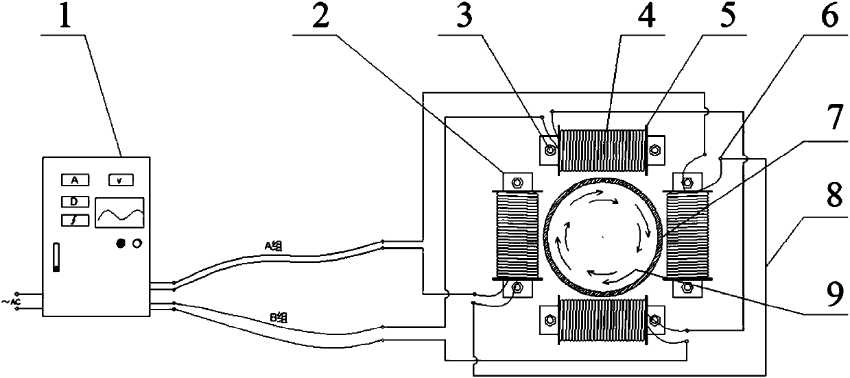
[0043] In the electromagnetic casting process, two sets of magnetic field application devices are arranged around the metal melt, the structure is as follows figure 1 Shown; Each magnetic field applying device comprises silicon steel sheet iron core 2, electromagnetic coil 4 and fixing device 3 (bolt nut), and the two ends of silicon steel sheet iron core 2 are fixed in the silicon steel sheet iron core cooling device 7 by fixing device 3, The silicon steel sheet core cooling device is provided with a cooling water inlet and a cooling water outlet; the electromagnetic coil 4 is wound on the silicon steel sheet iron core 2, and the two ends of the electromagnetic coil 4 are provided with an electromagnetic coil baffle 5, and the electromagnetic coil baffle 5 is fixed on the silicon steel On the sheet iron core 2, and the electromagnetic coil 4 is connected with the phase difference traveling wave magnetic field power supply system 1 through the connecting wire 8, and the connect...

Embodiment 2

[0054] Method is with embodiment 1, and difference is:

[0055] (1) Set up two sets of magnetic field application devices around the metal melt. The two magnetic field application devices are divided into A and B two sets of magnetic field application devices, which are called A1, A2, A3 and B1, B2, B3 respectively. Each set of magnetic field The application device is connected in series; the arrangement is as follows Figure 5 As shown in (b); every arbitrary 3 magnetic field applying devices constitute a group of magnetic field applying devices;

[0056] (2) The number of coil turns of each magnetic field applying device is 66 turns, which are arranged in two layers;

[0057] (3) The electromagnetic wire used by the electromagnetic coil is the winding wire of the submersible motor;

[0058] (4) Continuous casting is adopted, and the target product cast is an aluminum alloy billet;

[0059] Use the same method to carry out a comparative test without applying a magnetic fie...

Embodiment 3

[0061] Method is with embodiment 1, and difference is:

[0062] (1) The two magnetic field applying devices are divided into two groups of magnetic field applying devices, A and B, which are called A1~A4 and B1~B4 respectively, and each group of magnetic field applying devices is connected in series; the arrangement is as follows Figure 5 Shown in (a); every arbitrary 4 magnetic field application devices constitute a group of magnetic field application devices; the local structure is as Image 6 As shown, the location dimensions are as Figure 7 As shown, the silicon steel sheet iron core is fixed on the silicon steel sheet iron core cooling device by the silicon steel sheet iron core fixing bolt 10, 11, the outer cover of the silicon steel sheet iron core cooling device, 12, the inner sleeve of the silicon steel sheet iron core cooling device; The radius of r1 is between 25 and 300mm, the thickness of the inner sleeve of the silicon steel sheet iron core cooling device is b...


PUM

PropertyMeasurementUnit
thicknessaaaaaaaaaa
strengthaaaaaaaaaa

Abstract

The invention relates to an electromagnetic casting method of a difference phase traveling wave magnetic field. The electromagnetic casting method of the difference phase traveling wave magnetic fieldcomprises the following steps of during an electromagnetic casting process, arranging magnetic field applying devices on the periphery of a metal melt, and applying magnetic fields on the metal meltthrough the magnetic field applying devices during a metal melt inner sleeve casting process; forming a group of magnetic field applying devices through 2n magnetic field applying devices, and arranging two groups of magnetic field applying devices, wherein each group of magnetic field applying devices respective produces a group of pulse electromagnetic signals, and a phase angle difference of the two groups of electromagnetic pulse signals is 90 degrees; and forming the difference phase traveling wave magnetic field in the metal melt. According to the method provided by the invention, the function of the electromagnetic fields on an alloy melt is fully realized, the magnetic field control at different parts during a preparation process of blanks with different shapes and specifications is realized, a magnetic field refining effect is improved, temperature and components are uniform, the melt is purified, a structure and components of an alloy casting blank are remarkably improved, and a performance of an ingot casting is improved.

Description

technical field [0001] The invention belongs to the field of nonferrous metal material processing, and in particular relates to an electromagnetic casting method with a phase difference traveling wave magnetic field. Background technique [0002] With the continuous development of casting technology, people's requirements for casting quality have been continuously improved, and stricter standards have been put forward for the structure and properties of metals and alloys. The performance of casting alloys mainly depends on their solidification structure, and ordinary casting alloys have solidification structures. The shortcomings of developed dendrites, coarse grains, and uneven structure greatly reduce the mechanical properties and deformation capacity of the material; according to the Hall-Petch relationship, refining the grains can improve the mechanical properties of polycrystalline materials. Strength; therefore, it is of great significance to refine the grains in the m...

Claims


Application Information

Patent Timeline
Patent Type & Authority Applications(China)
IPC IPC(8): B22D27/02B22D11/115
CPCB22D11/115B22D27/02
Inventor 乐启炽贾永辉宋泽天廖启宇宝磊王彤
Owner NORTHEASTERN UNIV
Why Eureka
Try Eureka