Dry and wet mixed connection method of fabricated shear wall

A hybrid connection and shear wall technology, applied in the direction of walls, buildings, building components, etc., can solve the problems of difficult to guarantee the forming quality of reserved holes, difficult to guarantee welding quality, and difficult to guarantee the quality of grouting, so as to avoid welding operations and Auxiliary support, convenient on-site construction, and easy construction

Active Publication Date: 2019-08-16
TIANJIN UNIV RES INST OF ARCHITECTRUAL DESIGN & URBAN PLANNING +1
View PDF6 Cites 0 Cited by
  • Summary
  • Abstract
  • Description
  • Claims
  • Application Information

AI Technical Summary

Problems solved by technology

When the sleeve grouting connection method is used, the grouting effect is not good because the grouting needs to be done in a closed space, and the quality inspection is difficult, and the quality of the grouting is difficult to guarantee, and the steel sleeve needs to use high-strength steel, the processing process is complicated, and the cost Too high, high construction accuracy requirements, not suitable for steel bars with thinner cross-sections
The welded connection of steel bars has problems such as heavy welding workload on site and difficulty in guaranteeing welding quality.
The indirect lap joint grout-anchor connection has problems such as the difficulty of on-site construction and the difficulty in ensuring the quality of the reserved holes. Therefore, the prefabrication rate of the inner wall in the prefabricated structure is low, and the cast-in-place structure needs to be installed before reaching the preset strength after hoisting. temporary support

Method used


Image

  • Dry and wet mixed connection method of fabricated shear wall
  • Dry and wet mixed connection method of fabricated shear wall
  • Dry and wet mixed connection method of fabricated shear wall

Examples


Embodiment Construction

[0026] In order to further understand the invention content, characteristics and effects of the present invention, the following examples are given, and detailed descriptions are as follows in conjunction with the accompanying drawings:

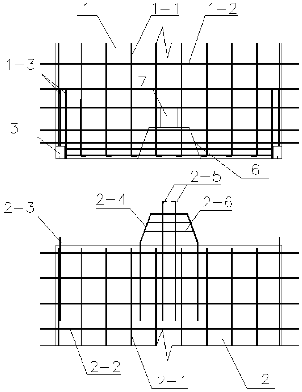
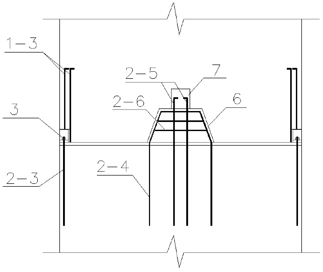
[0027] see Figure 1 to Figure 8 , a dry-wet hybrid connection method for prefabricated shear walls, in which a missing corner structure is provided at the four bottom corners of the upper prefabricated wall panel 1, and a steel bar connector 3 matching it is fixed in the missing corner structure, The steel bar connector 3 is provided with a vertically arranged angle steel section 3-1, and a horizontally arranged connecting bottom plate 3-2 is fixed on the bottom of the angle steel section 3-1, and the connecting bottom plate 3-2 is connected to the upper layer The bottom surface of the prefabricated wallboard 1 is flush, and bolt holes are provided on the connecting bottom plate 3-2. The middle position of the bottom of the bottom is provid...


PUM


Abstract

The invention discloses a fabricated shear wall dry-wet mixed connection method. The left ends and the right ends of upper-layer prefabricated wall plates and lower-layer prefabricated wall plates areconnected in a positioned mode through nuts, and then cast-in-place shearing force key structures are formed in the middles of the upper-layer prefabricated wall plates and the lower-layer prefabricated wall plates. According to the fabricated shear wall dry-wet mixed connection method, four steel bar connectors are arranged at the two ends of each upper-layer wall plate correspondingly, groovesare formed in the bottoms of the upper-layer prefabricated wall plates, concrete is poured into the grooves to form the shearing force key structures, connecting steel bars anchored on the lower-layerprefabricated wall plates are locked on the steel bar connectors, and thus the connecting structures of the upper-layer prefabricated wall plates and the lower-layer prefabricated wall plates are convenient to construct and reliable in performance; and the advantages of dry-type connection and wet-type connection are combined, the problems that as for an existing connecting mode, on-site construction is difficult, and the quality is not prone to being ensured are solved effectively, the construction process can be simplified, the assembling quality is improved, the mechanical performance of ashear wall after assembling is improved, and the purpose of reducing cost is achieved.

Description

technical field [0001] The invention relates to a connection method of a prefabricated shear wall, in particular to a dry-wet hybrid connection method of a prefabricated shear wall. Background technique [0002] Shear wall structure is an important component of high-rise buildings. It has high bearing capacity and stiffness against lateral movement, can effectively resist horizontal shear force, and has good seismic performance. In recent years, my country's construction industrialization and housing industrialization have accelerated, and the prefabricated shear wall structure has gradually attracted attention and been widely used. It has the advantages of less on-site wet work, convenient construction, less impact on the surrounding environment, and less investment in transportation resources and labor resources. , has a very broad application prospect in multi-storey and high-rise residential buildings in my country. Due to the large horizontal shear force and horizontal ...

Claims


Application Information

Patent Timeline
Patent Type & Authority Patents(China)
IPC IPC(8): E04B2/56
CPCE04B1/61E04B2/56
Inventor 张锡治李倩楠
Owner TIANJIN UNIV RES INST OF ARCHITECTRUAL DESIGN & URBAN PLANNING
Why Eureka
Try Eureka