Supercharge Your Innovation With Domain-Expert AI Agents!

Horizontal effective ground stress testing method considering drilling fluid pressure and testing device

A stress test, effective technology, applied in the direction of the measuring device, the force sensor in the hole of the force-bearing structure, the component of the measurement force, etc., can solve the cumbersome and complicated operation of the stress test method, hinder the accuracy of the stress, Problems such as success rate and test efficiency, and the influence of ground stress are not taken into account, so as to achieve the effect of facilitating popularization and application, simple structure, and simplified operation

Pending Publication Date: 2018-07-31
SICHUAN UNIV
View PDF0 Cites 0 Cited by
  • Summary
  • Abstract
  • Description
  • Claims
  • Application Information

AI Technical Summary

Problems solved by technology

The existing in-situ stress measurement mainly uses small-diameter boreholes to reduce the disturbance to the original rock stress, but whether it is a direct measurement method such as rigid inclusion stress gauge method, hydraulic fracturing method, etc., or an indirect measurement method such as casing stress The release method or aperture deformation method does not take into account the influence of drilling fluid pressure on the in-situ stress during the drilling process, and the existing in-situ stress test methods are relatively cumbersome and complicated in operation, which hinders the accuracy and success of in-situ stress measurement. Increased rate and test efficiency

Method used


Image

  • Horizontal effective ground stress testing method considering drilling fluid pressure and testing device
  • Horizontal effective ground stress testing method considering drilling fluid pressure and testing device
  • Horizontal effective ground stress testing method considering drilling fluid pressure and testing device

Examples


Embodiment 1

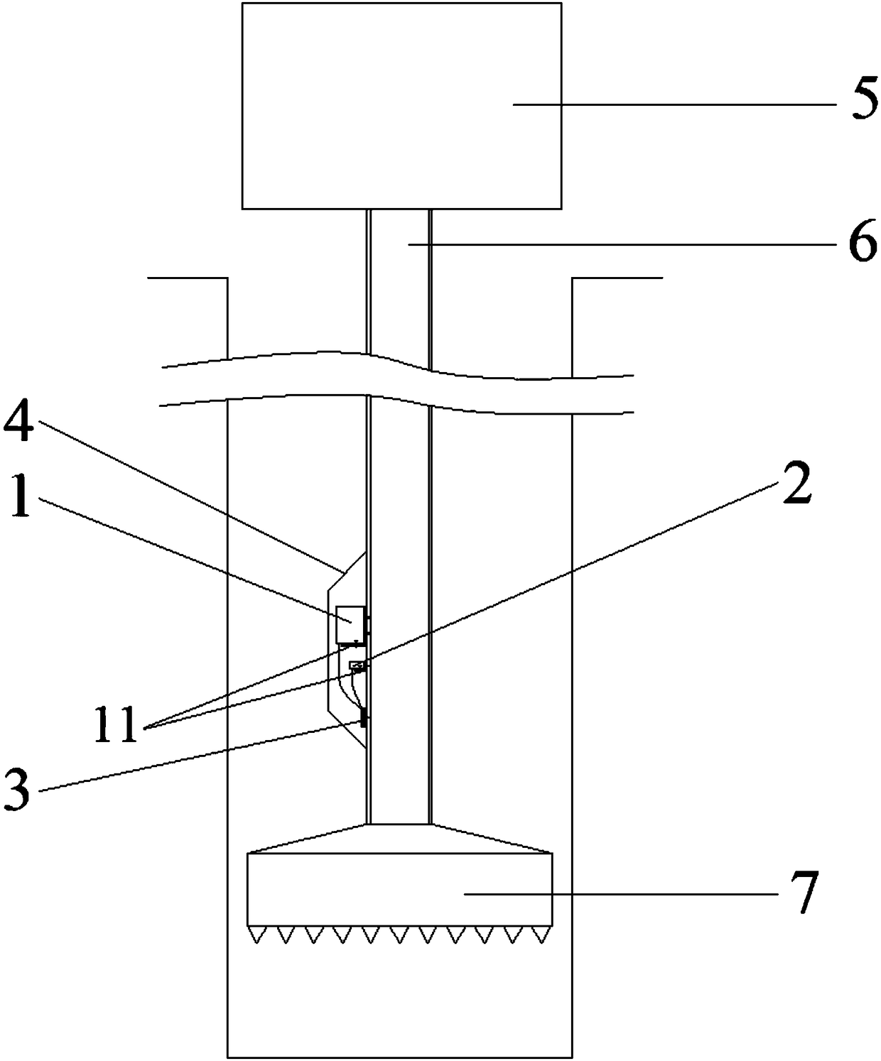
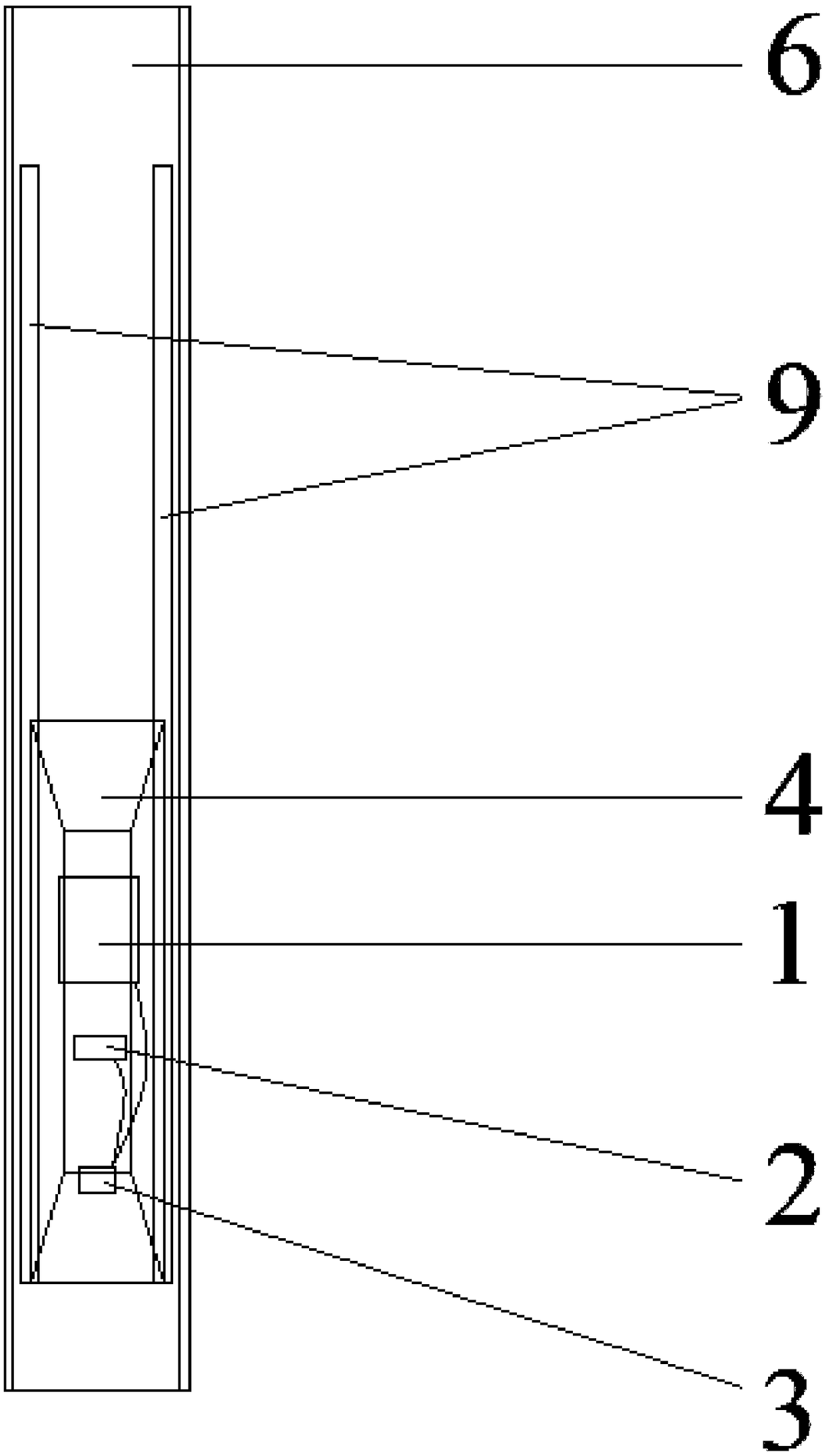
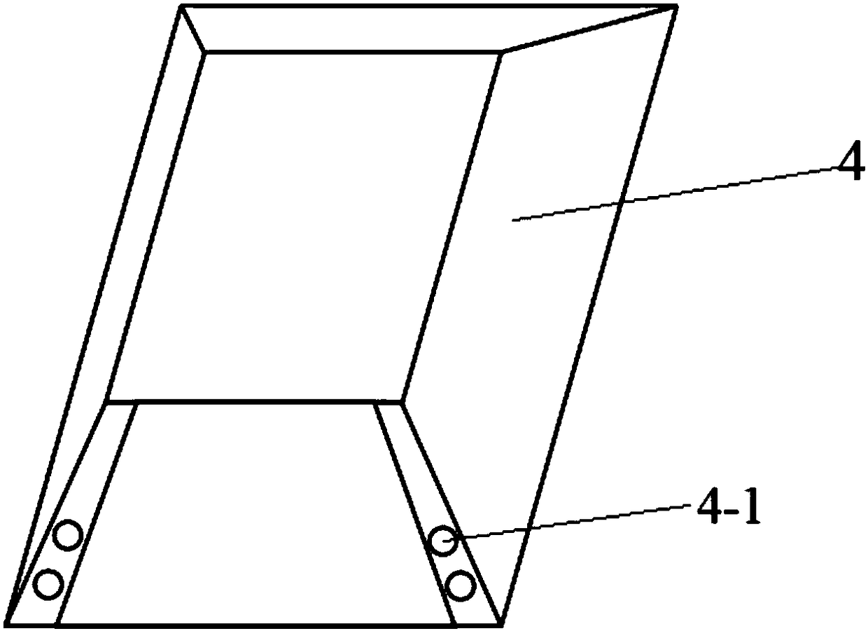
[0036] In this embodiment, the structure of the horizontally effective stress testing device is as follows figure 1 As shown, the horizontal effective stress test device is suitable for testing horizontal effective stress in boreholes perpendicular to the horizontal plane, including a multi-scale phase laser rangefinder 1, a three-dimensional electronic compass 2, and a multi-scale laser for integrating and storing Phase laser rangefinder 1 and three-dimensional electronic compass 2 data memory 3 for measurement data, transparent protective cover 4, drilling machine 5, drill pipe 6 and drill bit 7, the drill pipe includes several pieces, and each drill pipe is connected by thread, The drill bit 7 is connected with the drilling machine 5 through the drill rod 6. The diameter of the drilled hole drilled by the drill bit is 9cm larger than the outer diameter of the drill rod. and measurement accuracy requirements, you can choose to buy from the market, or you can choose to custom...

Embodiment 2

[0039] In this embodiment, the structure of the horizontally effective stress testing device is similar to figure 1 , the horizontal effective stress testing device is suitable for testing the horizontal effective stress in a borehole perpendicular to the horizontal plane, including a multi-scale phase laser rangefinder 1, a three-dimensional electronic compass 2, and a multi-scale phase laser for integrating and storing The data memory 3 of the measurement data of the rangefinder 1 and the three-dimensional electronic compass 2, the transparent protective cover 4, the drilling rig 5, the drill rod 6 and the drill bit 7, the drill rods include several roots, and the drill rods are connected by threads, and the drill bit 7 The drill rod 6 is connected with the drilling machine 5, and the diameter of the drilled hole drilled by the drill bit is 10 cm larger than the outer diameter of the drill rod. The measurement accuracy of the multi-light ruler phase laser range finder 1 is 2....

Embodiment 3

[0042] In this embodiment, a horizontal effective stress testing method considering the drilling fluid pressure is provided. The method uses the horizontal effective stress testing device in Embodiment 1 or 2 for testing, and the steps are as follows:

[0043] ①Determine the target rock mass to be subject to horizontal effective in-situ stress, explore or consult the lithology of the rock formations at different depths of the target rock mass according to the exploration data, and use indoor uniaxial compression tests to measure the elastic modulus and Poisson's ratio of rock formations at different depths;

[0044] ② Drill a hole perpendicular to the horizontal plane on the target rock mass. During the drilling process, the drilling fluid is passed to cool the drill bit. When the position of the multi-scale phase laser rangefinder in the hole reaches the target depth, the drilling is stopped. , check the position of the drill pipe in the drill hole, ensure that the axis of the...


PUM


Abstract

The invention provides a horizontal effective ground stress testing device which comprises a multi-light ruler phase laser range finder, a three-dimensional electronic compass, a data storage unit, atransparent protective cover, a drilling machine, a drill stem and a drill bit, wherein the multi-light ruler phase laser range finder, the three-dimensional electronic compass and the data storage unit are arranged on an outer wall of the drill stem; the multi-light ruler phase laser range finder and the three-dimensional electronic compass are horizontally mounted; both the multi-light ruler phase laser range finder and the three-dimensional electronic compass are connected with the data storage unit by virtue of data lines; the transparent protective cover is positioned on an outer wall ofthe drill stem and covers the multi-light ruler phase laser range finder, the three-dimensional electronic compass and the data storage unit; the drill bit is connected with the drilling machine by virtue of the drill stem. The invention further provides a horizontal effective ground stress testing method considering a drilling fluid pressure. According to the method, the horizontal effective ground stress testing accuracy can be improved, the testing operation is simplified, the testing success rate is improved, and the testing cost is reduced.

Description

technical field [0001] The invention belongs to the field of geostress testing, and relates to a horizontal effective geostress testing method and a testing device considering drilling fluid pressure. Background technique [0002] In-situ stress is the natural stress that exists in the formation without engineering disturbance, also known as the initial stress of rock mass, absolute stress or original rock stress, which is caused by mining, water conservancy and hydropower, civil engineering, railways, highways and other various underground or open-air stresses. The fundamental force of deformation and failure of rock excavation engineering is the premise of determining the mechanical properties of engineering rock mass, analyzing the stability of engineering rock mass, and realizing scientific design and decision-making of rock mass engineering. The state of in-situ stress is of great significance for earthquake prediction, evaluation of regional crustal stability, research...

Claims


Application Information

Patent Timeline
IPC IPC(8): G01L5/00G01L5/16
CPCG01L5/0004G01L5/16Y02A90/30
Inventor 高明忠陆彤吕有厂张建国汪文勇刘强陈海亮彭高友王明耀王飞
Owner SICHUAN UNIV
Features
  • R&D
  • Intellectual Property
  • Life Sciences
  • Materials
  • Tech Scout
  • Unparalleled Data Quality
  • Higher Quality Content
  • 60% Fewer Hallucinations
Learn More