Ventilator

A ventilator and breathing gas technology, which is applied in the field of ventilators, can solve the problems of unsuitable breathing equipment for mobile operation, paramagnetic oxygen sensor sensitivity, etc., and achieve the effects of saving structural space and weight, economic life, and long life

Active Publication Date: 2018-07-31
欧根卡根
View PDF14 Cites 9 Cited by
  • Summary
  • Abstract
  • Description
  • Claims
  • Application Information

AI Technical Summary

Problems solved by technology

However, especially when using delicate mechanical components, paramagnetic oxygen sensors a...

Method used


Image

  • Ventilator
  • Ventilator
  • Ventilator

Examples


Embodiment Construction

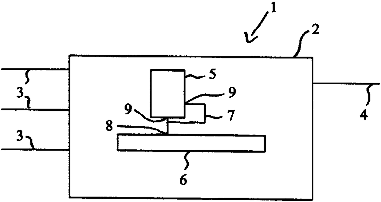
[0040] figure 1A ventilator 1 for supplying breathing gas to a patient is shown. The ventilator 1 has a housing 2 which contains connections for a supply line 3 for compressed gas, not shown in detail. In particular oxygen and compressed air are conceivable as this compressed gas, wherein the compressed air can be obtained from pressurized gas cylinders, a hospital compressed gas supply or a turbine. Oxygen can be obtained, inter alia, from pressurized gas cylinders or from a hospital's compressed gas supply.

[0041] Furthermore, the ventilator 1 has a line 4 via which the patient is supplied with breathing gas. The breathing gas is mixed inside the housing 2 of the ventilator 1 from the gas supplied via the inlet line 3 . In this case, in particular the composition, pressure and temperature of the breathing gas can be regulated in a predetermined manner.

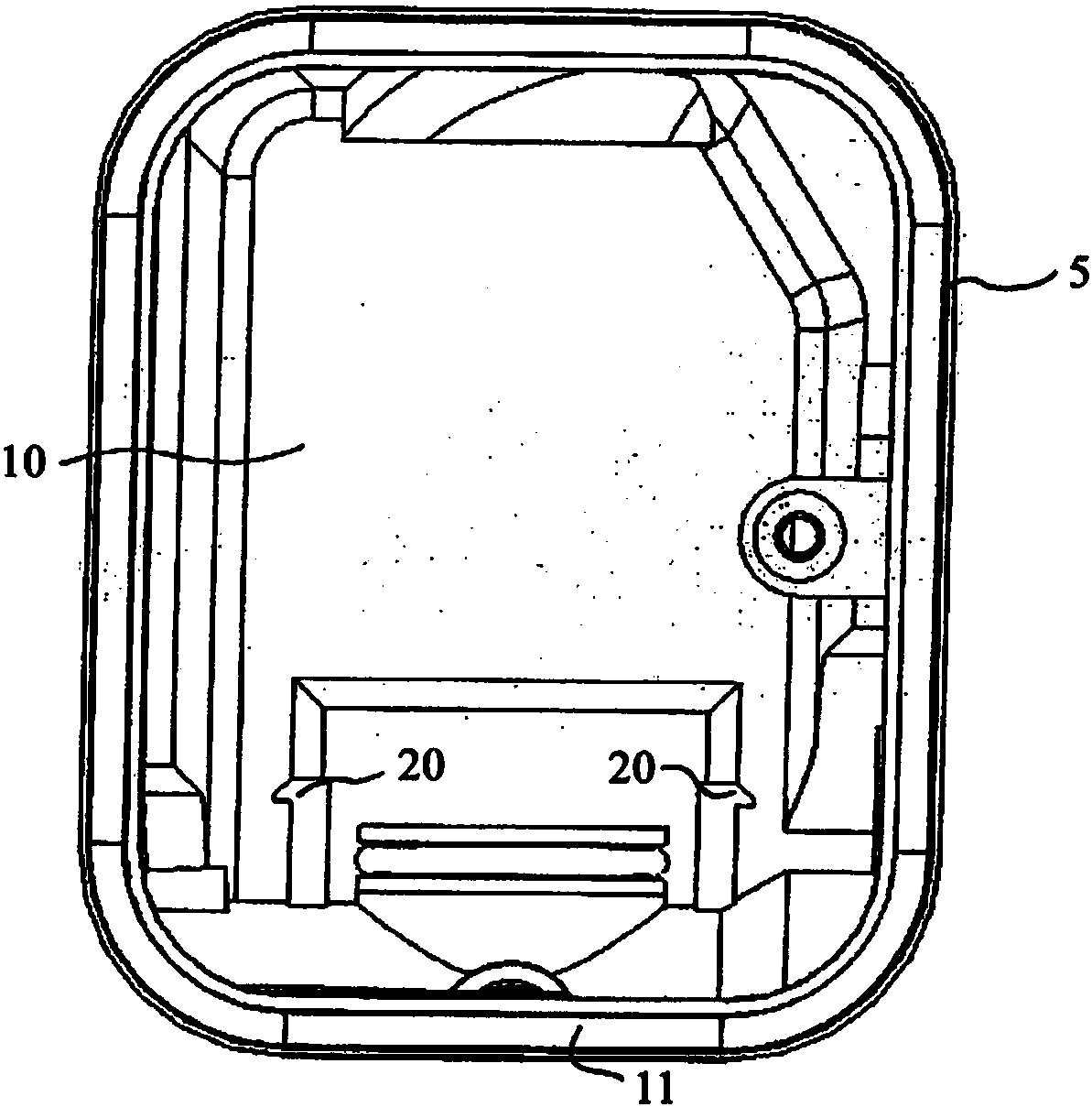
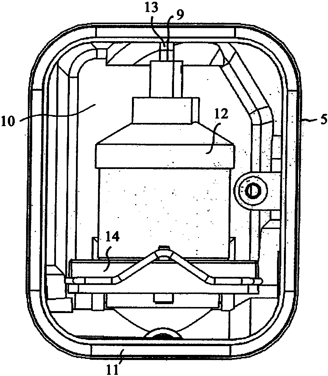
[0042] A receptacle 5 for an oxygen sensor is provided in the housing 2 . The sensor installed in the receptacle 5 ...


PUM


Abstract

A ventilator (1) comprises a gas pipe system for supplying respiratory gas to a patient; at least one monitoring device is provided for monitoring the oxygen concentration in the respiratory gas; saidmonitoring device includes at least one receptacle (5) for an oxygen sensor (12, 15); a galvanic oxygen sensor (12) or a paramagnetic oxygen sensor (15) can be selectively inserted into the receptacle (5).

Description

technical field [0001] The invention relates to a ventilator with a gas conduit system for supplying breathing gas to a patient. Background technique [0002] Such a breathing apparatus is known, for example, from DE 10 2006 055 779 B3. It consists of an inlet line, in particular for oxygen and compressed air mixed in a preset manner in a breathing apparatus, and a conduit, by means of which the mixed, conditioned and kept at the preset Breathing gas at a given pressure level can be delivered to the patient. Such respiratory devices usually have at least one oxygen sensor for monitoring the oxygen content of the breathing gas. The oxygen sensor can be arranged in the region of the catheter leading to the patient, in the region of the mixing chamber or in other regions of the catheter system. Multiple oxygen sensors may also be provided. [0003] In medical ventilators, amperometric, also referred to as “electrochemical” oxygen sensors are generally used, in which oxygen,...

Claims


Application Information

Patent Timeline
IPC IPC(8): A61M16/00G01N33/497
CPCG01N33/497A61M2202/0208A61M2230/205A61M16/024G01N27/10G01R33/12A61M16/0003A61M16/1005A61M2016/1025
Inventor 欧根·卡根
Owner 欧根卡根
Why Eureka
Try Eureka