

T spline surface-based porous sandwich structure and application
A spline surface and porous structure technology, applied in special data processing applications, instruments, electrical digital data processing, etc., can solve the problems of difficult and efficient generation of porous sandwich structures, undiscovered design methods, etc., to achieve stable and reliable generation methods, High continuity and smoothness, the effect of reducing the consumption of manufacturing materials
- Summary
- Abstract
- Description
- Claims
- Application Information
AI Technical Summary
Problems solved by technology
Method used
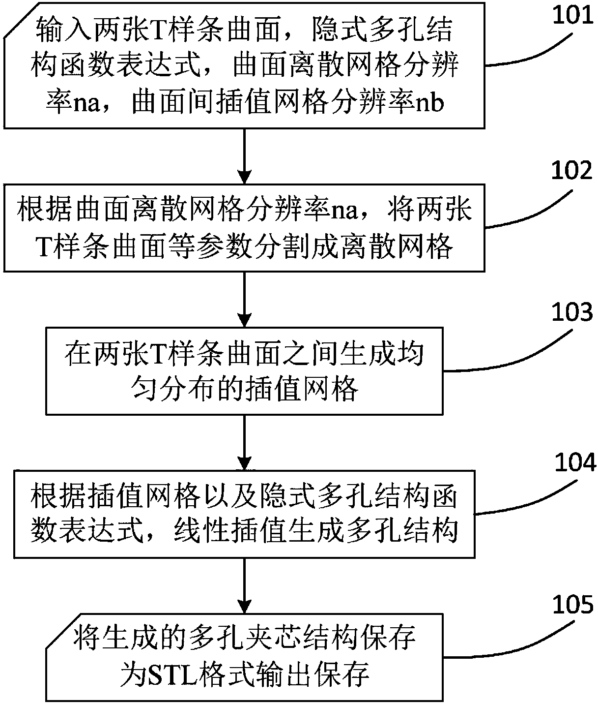
Image

Examples
Embodiment 1
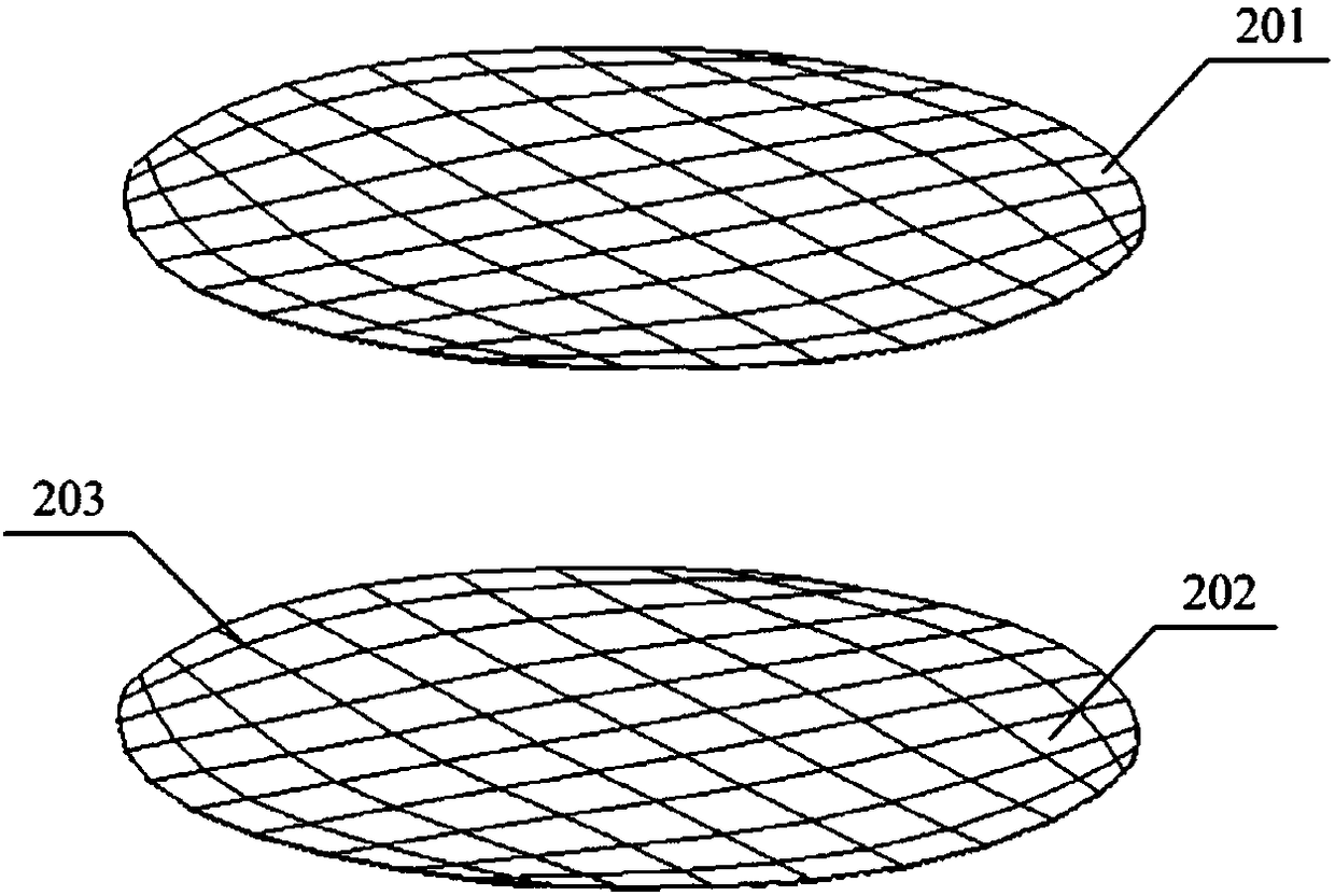
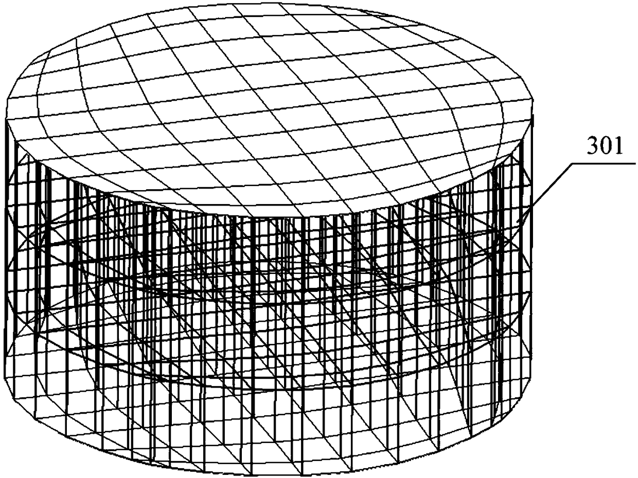
[0061] Select the vibration isolation layer of special-shaped mechanical parts to design and generate a porous sandwich structure. In order to closely fit complex special-shaped mechanical parts, use T-spline surface to model the two surfaces of adjacent parts, and generate a porous sandwich structure between the surfaces of the two parts , which can realize the vibration isolation function between mechanical parts in complex motion conditions. The expression of the implicit porous structure function is:
[0062] 10×(cosxsiny+cosysinz+coszsinx)-0.5×[cos(2x)×cos(2y)+cos(2y)×cos(2z)+cos(2z)×cos(2x)]-14=0, na= 80, nb=80.
[0063] Such as Figure 5 As shown, an ordered porous sandwich structure is designed and generated between two T-spline free-form surfaces. The generated structure is saved as an STL model and manufactured by rapid prototyping technology, which plays an ideal role in vibration isolation.
Embodiment 2
[0065] The wing panel is selected to generate a lightweight porous sandwich structure. The complex free-form surfaces of the wing upper panel and the lower panel are modeled and designed by T-spline surface respectively. The expression of the implicit porous structure function is selected as: 0.5×[sin (2x)×cos(y)×sin(z)+sin(2y)×cos(z)×sin(x)+sin(2z)×cos(x)×sin(y)]-0.5×[cos( 2x)*cos(2y)+cos(2y)*cos(2z)+cos(2z)*cos(2x)]+0.15=0, na=80, nb=80.
[0066] Such as Image 6 As shown, the method of the present invention is used to generate a lightweight porous sandwich structure between the free curved surfaces of the upper and lower wall panels of the wing, which can reduce material consumption and energy consumption while satisfying mechanical properties. The sandwich structure designed and generated is manufactured using additive manufacturing technology. Compared with the solid wall plate structure of the same material and size, the porous sandwich structure designed and manufactur...
PUM
 Abstract
Description
Claims
Application Information