Calculation method for the expansion behavior of composite delamination defects in the chisel-edge extrusion stage

A technology of delamination defects and calculation methods, applied in design optimization/simulation, geometric CAD, special data processing applications, etc., can solve the problem that delamination expansion behavior cannot be applied to the hole making process of carbon fiber composite materials, the drilling force is not constant, Problems such as the uncontrollable position of the tool and the defect

Active Publication Date: 2020-04-28
DALIAN UNIV OF TECH
View PDF5 Cites 0 Cited by
  • Summary
  • Abstract
  • Description
  • Claims
  • Application Information

AI Technical Summary

Problems solved by technology

However, the actual drilling process is a dynamic process under the continuous feeding of the tool. The drilling force is not constant and the position of the action point changes dynamically with the rotation and feeding motion of the cutting edge. In addition, due to the randomness of the distribution of forming defects, The actual action position of the tool and the defect is uncontrollable
Therefore, the research on the delamination expansion behavior under static load cannot be applied to the hole-making process of carbon fiber composite materials, and it is necessary to study the expansion behavior of carbon fiber composite material forming defects during drilling.

Method used


Image

  • Calculation method for the expansion behavior of composite delamination defects in the chisel-edge extrusion stage
  • Calculation method for the expansion behavior of composite delamination defects in the chisel-edge extrusion stage
  • Calculation method for the expansion behavior of composite delamination defects in the chisel-edge extrusion stage

Examples


Embodiment Construction

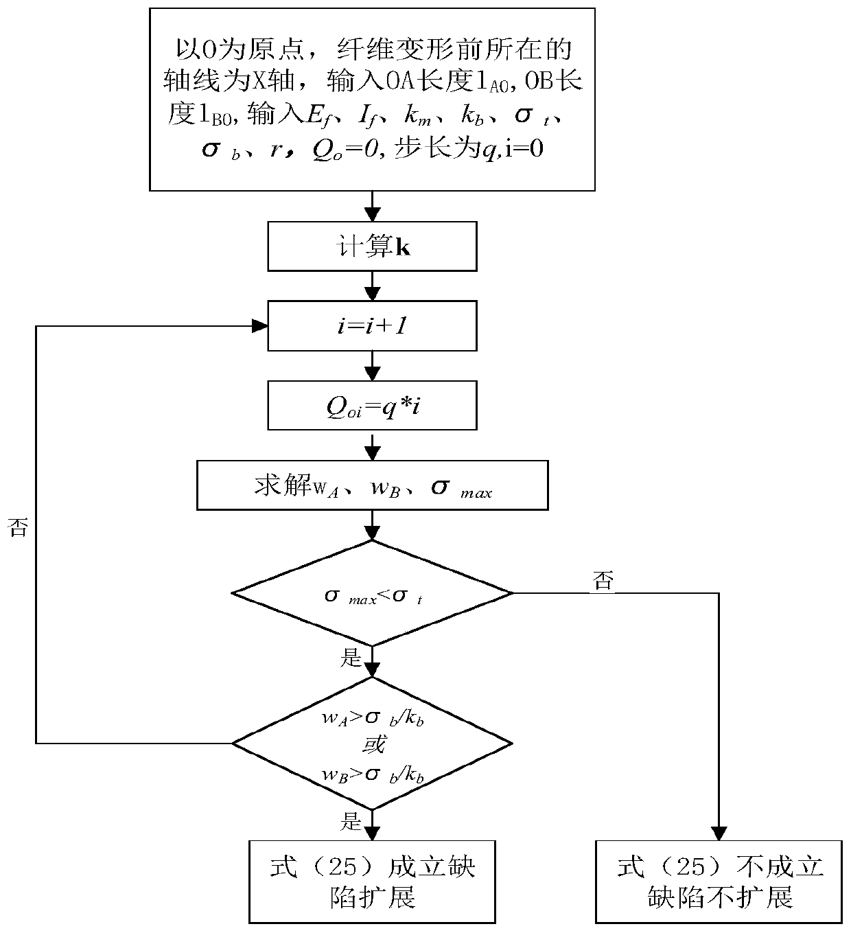
[0067] The specific implementation of the present invention will be described in detail below in conjunction with the technical scheme and accompanying drawings.

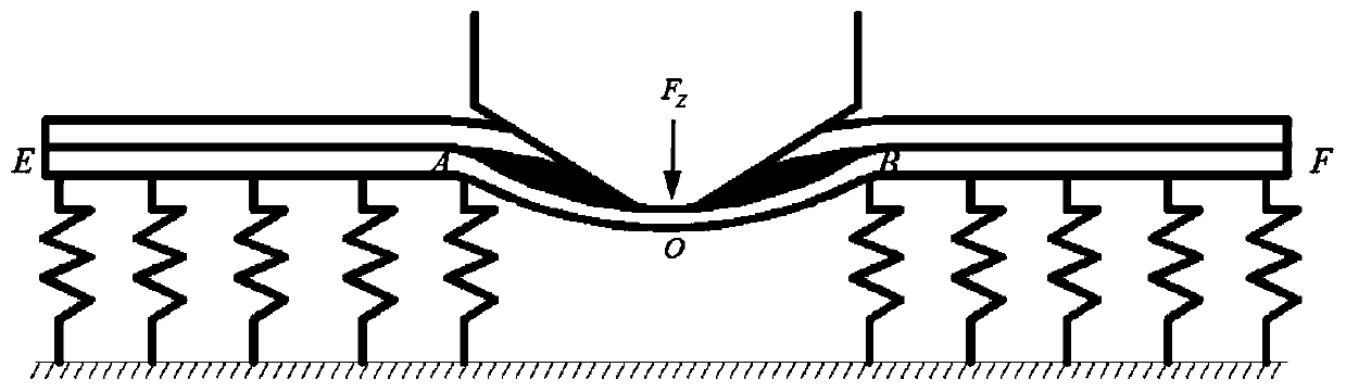
[0068] 1) Input the performance parameters of the material to be processed, the position of the tool, and the size of the forming layer defect. What is used in this example is T800 / 977-2 prepreg, the Young's modulus E of the fiber in the prepreg f is 295GPa, the fiber tensile strength σ t is 4.5GPa, fiber radius r is 3.25μm, fiber equivalent modulus k b 115GPa, resin bond strength σ b is 50pa m, the equivalent modulus of the surrounding material It is 9.65Gpa, and the Poisson's ratio υ of the surrounding material is 0.3. The center of the tool is 0.1mm away from the left edge of the defect, and the size and shape of the forming delamination defect contained in the component is a circle with a diameter of 7mm.

[0069] 2) Simplify the extrusion process of the chisel edge on the defective layer as the bending pr...


PUM


Abstract

The invention discloses a method for calculating extension behaviors of lamination defects of composite materials in a chisel edge extrusion stage, belongs to the technical field of machining, and relates to a method for calculating extension behaviors of molding lamination defects in carbon fiber composite material components in a drilling chisel edge extrusion stage. The method comprises the following steps of: simplifying a process of extruding a defect layer by a chisel edge into a bending process of an elastic foundation beam under the action of a centralized load, and solving a bending deformation control equation of the beam; determining a cutter action position and a molding lamination defect size, carrying out region division on a fiber in the defect layer according to a constraint condition and a stress characteristic, and obtaining an overall rigidity matrix of the whole fiber by utilizing a finite element calculation method and a superposition principle; and finally calculating a critical condition and an extension length of extension of the molding lamination defect by adoption of a manner of carrying out gradual loading to a cutter action point. The method is suitablefor calculating the extension behaviors of molding lamination defects which are located at different machining positions and have different sizes and shapes, so as to restrain the extension of the lamination defects and ensure the final hole making quality.

Description

technical field [0001] The invention belongs to the technical field of mechanical processing, and relates to a calculation method for the expansion behavior of forming delamination defects inside a carbon fiber composite material component during the chisel edge extrusion stage of drilling, and is a method for suppressing further expansion of internal defects of components during mechanical processing method. Background technique [0002] Carbon fiber composite load-bearing components are often designed and manufactured by integrating laying, curing, and processing. Compared with the manufacturing method of traditional material components, the process flow is effectively shortened and the production efficiency is greatly improved. However, due to the anisotropy of carbon fiber composites, the characteristics of laminated molding, and the non-uniformity of thermal and chemical shrinkage during hot-press curing, it is prone to delamination defects during the molding process. ...

Claims


Application Information

Patent Timeline
Patent Type & Authority Patents(China)
IPC IPC(8): G06F30/23G06F30/17
CPCG06F30/17G06F30/23
Inventor 王福吉胡海波张博宇马建伟赵猛
Owner DALIAN UNIV OF TECH
Why Eureka
Try Eureka