Microstrip period meander line slow-wave structure

A zigzag slow wave and zigzag line technology, applied in the field of microwave electric vacuum electronic devices, can solve problems such as processing difficulties, and achieve the effects of reduced processing difficulty, high coupling impedance and good thermal conductivity

Active Publication Date: 2018-08-10
UNIV OF ELECTRONICS SCI & TECH OF CHINA
View PDF6 Cites 6 Cited by
  • Summary
  • Abstract
  • Description
  • Claims
  • Application Information

AI Technical Summary

Problems solved by technology

[0006] However, because the dielectric support rod needs to undergo the same bending as the meandering metal strip, that is, the same transformation cycle, its processing is more difficult. Secondly, the coupling impedance can be further improved

Method used


Image

  • Microstrip period meander line slow-wave structure
  • Microstrip period meander line slow-wave structure
  • Microstrip period meander line slow-wave structure

Examples


Embodiment Construction

[0023] The specific embodiments of the present invention are described below with reference to the accompanying drawings, so that those skilled in the art can better understand the present invention. It should be noted that, in the following description, when the detailed description of known functions and designs may dilute the main content of the present invention, these descriptions will be omitted here.

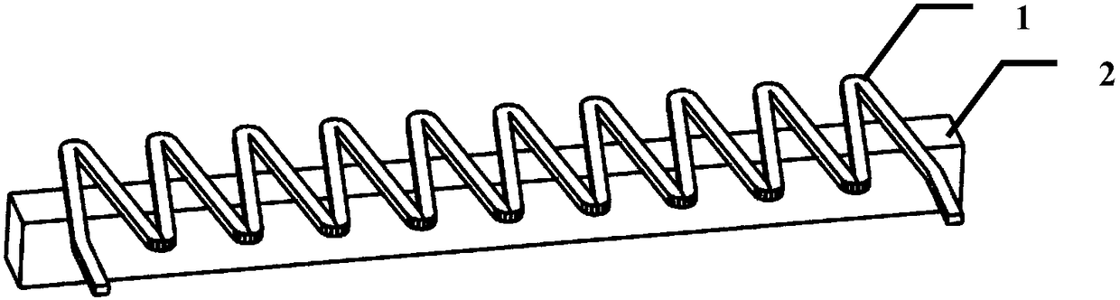
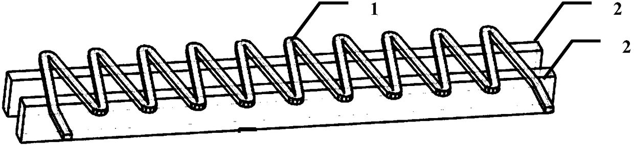
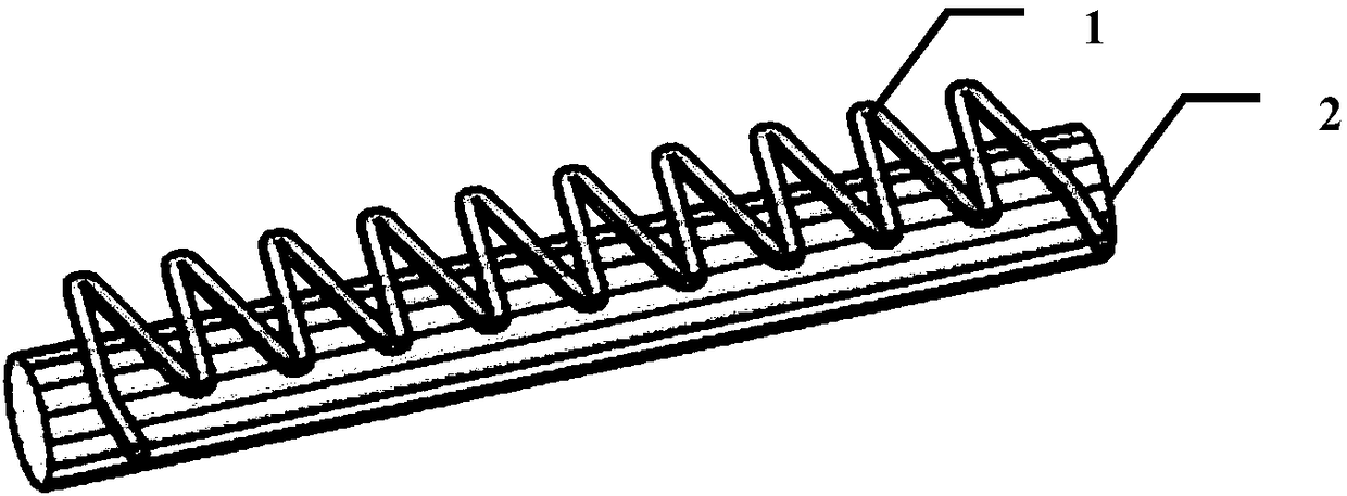
[0024] Aiming at the difficulty of processing the periodic microstrip meander line in the current millimeter wave plane traveling wave tube, the present invention proposes a structure that utilizes a straight line structure to support the periodic microstrip meander line in the plane traveling wave tube. The periodic microstrip zigzag line is a V-shaped or U-shaped structure extending on the plane. The dielectric support rod is located below the periodic microstrip zigzag line of the V-shaped or U-shaped structure, which plays the role of support and heat dissipation. The ...


PUM


Abstract

The invention discloses a microstrip period meander line slow-wave structure. A dielectric support rod of a linear structure supports the periodic microstrip meander line, the processing difficulty isreduced greatly, and the design flexibility is increased. A present meandering dielectric support rod cannot be realized without a semiconductor technology and uses a silicon substrate, and the dielectric support rod in the structure of the invention is made of a diamond material, the effective dielectric constant (5.7) of diamond is lower than that (11.5) of silicon, and the coupling impedance of the dielectric support rod of the diamond material is higher compared with that of silicon. In addition, the dielectric support rod of the linear structure directly supports the lower surface of theperiod microstrip meander line instead of embedding the meandering band-shaped dielectric support rod, so that a heat radiation problem in the microstrip period meander line slow-wave structure becomes serious, and the diamond of high thermal conductivity can be used to solve the problem.

Description

technical field [0001] The invention belongs to the technical field of microwave electric vacuum electronic devices, and more particularly relates to a microstrip period meandering slow wave structure used in vacuum electronic devices such as traveling wave tubes, klystrons and high frequency and high power microwave devices. Background technique [0002] Planar traveling wave tube is an important development direction of miniaturized traveling wave tube. The slow wave structure it adopts is relatively simple, and it is composed of thin conductor strips (microstrips) engraved on a flat dielectric substrate. This planar slow-wave structure generally uses a ribbon electron beam to increase the total current intensity without increasing the current density. This type of traveling wave tube has the advantages of small size, light weight and low cost. [0003] The existing microstrip periodic meander line slow wave structure is formed by repeating a plane metal line on a flat di...

Claims


Application Information

Patent Timeline
Patent Type & Authority Applications(China)
IPC IPC(8): H01J23/24
CPCH01J23/24
Inventor 曹华崔灿王战亮宫玉彬黄华徐雄
Owner UNIV OF ELECTRONICS SCI & TECH OF CHINA
Why Eureka
Try Eureka