

Chopper for improving bonding strength of lead
A technology of wire bonding and riving, which is applied in the field of riving, can solve the problems of insufficient bonding strength of wire and wire, insufficient surface roughness, easy wear, etc., and achieve reduced gold retention at the tip, good bonding effect, and smoothness high effect
- Summary
- Abstract
- Description
- Claims
- Application Information
AI Technical Summary
Problems solved by technology
Method used
Image

Examples
Embodiment 1
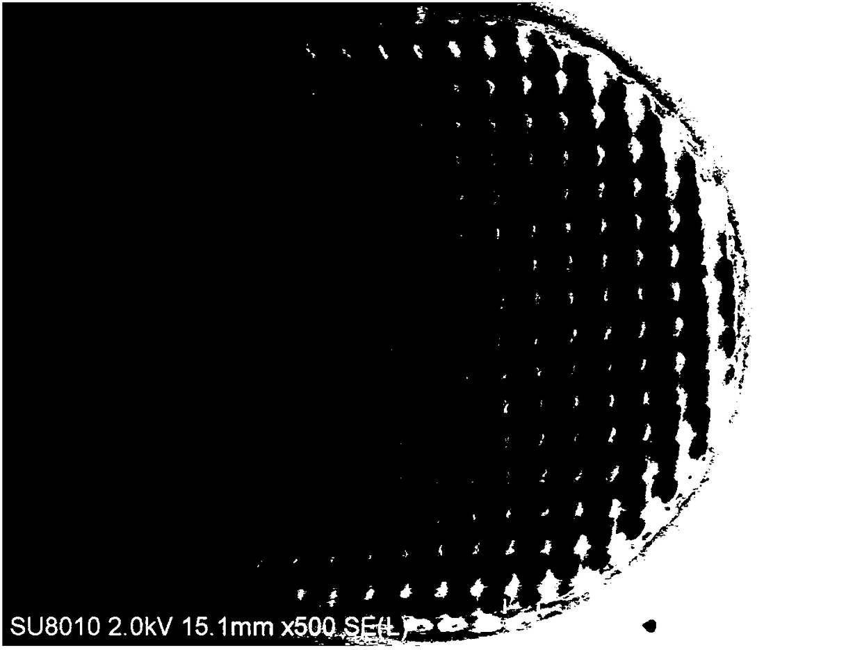
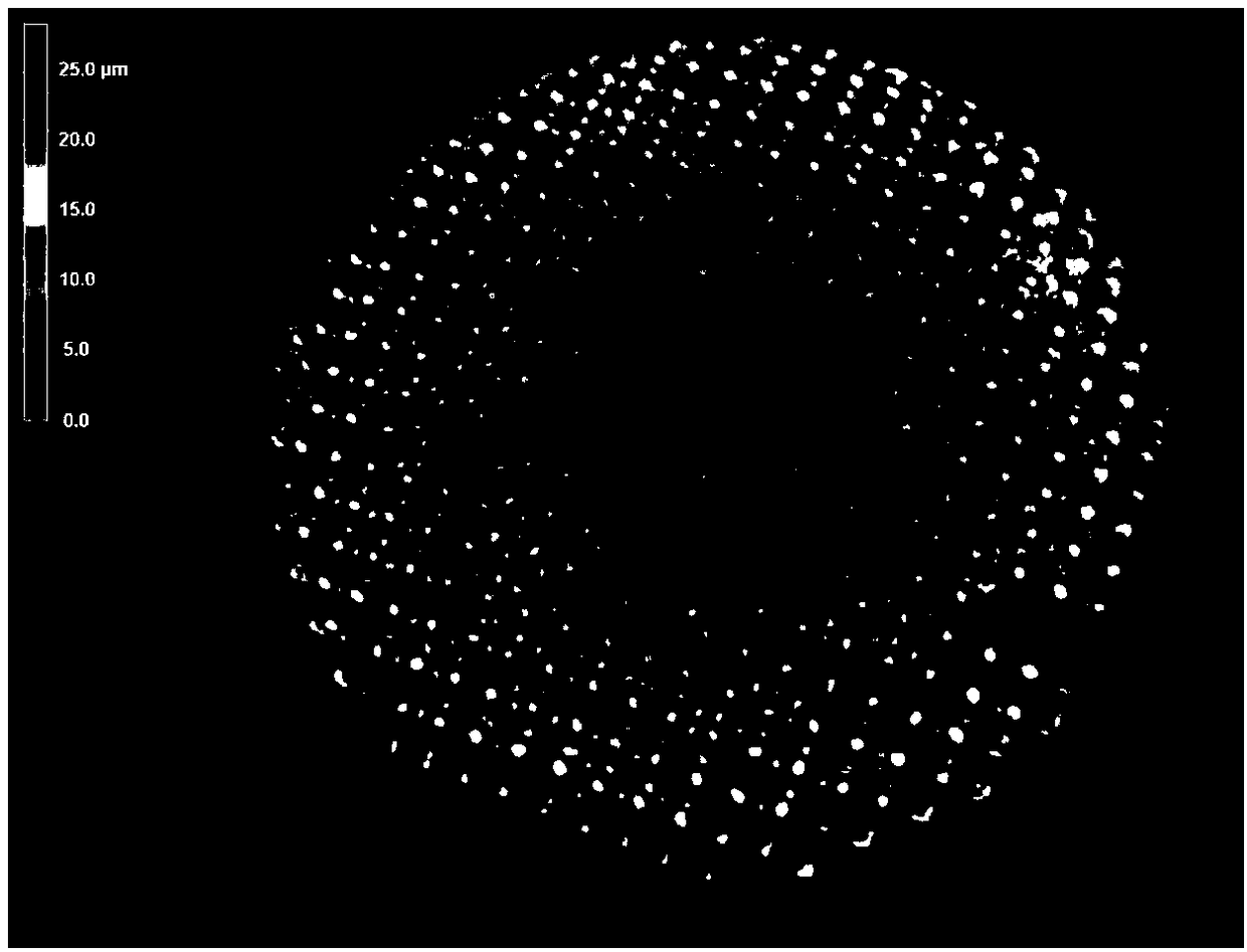
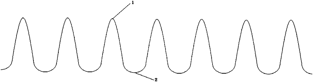
[0033] A kind of embodiment of the capillary that improves wire bonding strength described in the present invention, the scanning electron microscope photo of the end face surface of the capillary that improves wire bonding strength described in this embodiment is as follows figure 1 As shown, the 3D laser microscope photo of the end face of the chopper is as follows figure 2 As shown, the local structure of the tip surface of the chopper tip is shown in image 3 As shown, a structural diagram of the chopper is shown in Figure 4 Shown:
[0034] The rivet is a welding ceramic rivet, and the rivet includes a body 41, a welding nozzle 42 at one end of the body and a hole 43, the hole 43 extends along the longitudinal axis of the body 41 and the welding nozzle 42, and the tip surface of the welding nozzle 42 is formed by Composed of alternately distributed convex parts 1 and concave parts 2; the convex parts 1 and the concave parts 2 are uniformly and alternately distributed; ...
Embodiment 2
[0036] A kind of embodiment of the capillary that improves wire bonding strength described in the present invention, the scanning electron microscope photo of the end face surface of the capillary that improves wire bonding strength described in this embodiment is as follows figure 1 As shown, the 3D laser microscope photo of the end face of the chopper is as follows figure 2 As shown, the local structure of the tip surface of the chopper tip is shown in image 3 As shown, a structural diagram of the chopper is shown in Figure 4 Shown:
[0037] The rivet is a welding ceramic rivet, and the rivet includes a body 41, a welding nozzle 42 at one end of the body and a hole 43, the hole 43 extends along the longitudinal axis of the body 41 and the welding nozzle 42, and the tip surface of the welding nozzle 42 is formed by Composed of alternately distributed convex parts 1 and concave parts 2; the convex parts 1 and the concave parts 2 are uniformly and alternately distributed; ...
Embodiment 3
[0039] A kind of embodiment of the capillary that improves wire bonding strength described in the present invention, the scanning electron microscope photo of the end face surface of the capillary that improves wire bonding strength described in this embodiment is as follows figure 1 As shown, the 3D laser microscope photo of the end face of the chopper is as follows figure 2 As shown, the local structure of the tip surface of the chopper tip is shown in image 3 As shown, a structural diagram of the chopper is shown in Figure 4 Shown:
[0040] The rivet is a welding ceramic rivet, and the rivet includes a body 41, a welding nozzle 42 at one end of the body and a hole 43, the hole 43 extends along the longitudinal axis of the body 41 and the welding nozzle 42, and the tip surface of the welding nozzle 42 is formed by Composed of alternately distributed convex parts 1 and concave parts 2; the convex parts 1 and the concave parts 2 are uniformly and alternately distributed; ...
PUM
| Property | Measurement | Unit |
|---|---|---|
| Height | aaaaa | aaaaa |
| Lateral distance | aaaaa | aaaaa |
| Roughness | aaaaa | aaaaa |
Abstract
Description
Claims
Application Information