Ankle and foot orthopedic device and method for controlling same

An ankle-foot and orthopedic technology, applied in the field of ankle-foot orthopedic device and its control, can solve the problems that the ankle cannot adapt to the changes of different synchronicity, the force demand of different people, etc., and achieve the effect of high cost performance, compact structure and convenient installation.

Inactive Publication Date: 2018-08-14
THE WEST CHINA SECOND UNIV HOSPITAL OF SICHUAN
View PDF13 Cites 13 Cited by
  • Summary
  • Abstract
  • Description
  • Claims
  • Application Information

AI Technical Summary

Problems solved by technology

[0006] The present invention aims to solve the technical problem that the ankle cannot adapt to different gait changes and different people's demand for force in the existing ankle-foot orthotic device, and provides an ankle-foot orthotic device and its control method, through pneumatic artificial muscles, sensors and The combination of intelligent algorithms solves the problems of weight, convenience and adaptive control of the current ankle-foot orthotics, and can bas

Method used


Image

  • Ankle and foot orthopedic device and method for controlling same
  • Ankle and foot orthopedic device and method for controlling same
  • Ankle and foot orthopedic device and method for controlling same

Examples


Embodiment 1

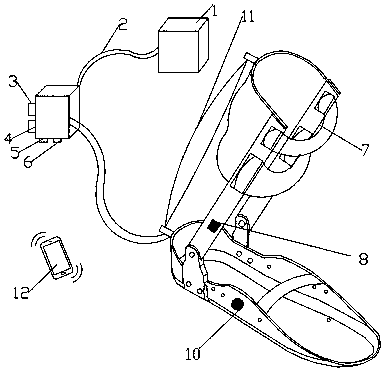
[0080]First connect one end of a trachea 2 to the air outlet of the air compressor, and the other end to the air inlet of the proportional valve 3, then use a trachea 2 to connect the air outlet of the proportional valve 3, and the other end to the pneumatic artificial muscle 11 The air inlet forms a pneumatic passage; the 24V DC output terminal of the switching power supply is connected to the positive pole of the power supply corresponding to the proportional valve 3 cable, and the ground wire is connected to the COM terminal of the switching power supply. Then connect a long enough power cord in parallel to the 24V DC output terminal of the switching power supply and connect it to the TPS5430 power conversion module. The Bluetooth module and AMS1117-3.3 module, the 3.3V DC output of the AMS1117-3.3 module is connected to the STM32 microcontroller. When the switching power supply input terminal is connected to 220V AC, the whole device is powered on.

[0081] Such as Figur...

Embodiment 2

[0085] First connect one end of a trachea 2 to the air outlet of the air compressor, and the other end to the air inlet of the proportional valve 3, then use a trachea 2 to connect the air outlet of the proportional valve 3, and the other end to the pneumatic artificial muscle 11 The air inlet forms a pneumatic passage; the 24V DC output terminal of the switching power supply is connected to the positive pole of the power supply corresponding to the proportional valve 3 cable, and the ground wire is connected to the COM terminal of the switching power supply. Then connect a long enough power cord in parallel to the 24V DC output terminal of the switching power supply and connect it to the TPS5430 power conversion module. The Bluetooth module and AMS1117-3.3 module, the 3.3V DC output of the AMS1117-3.3 module is connected to the STM32 microcontroller. When the switching power supply input terminal is connected to 220V AC, the whole device is powered on.

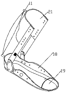
[0086] Such as imag...

Embodiment 3

[0090] First connect one end of a trachea 2 to the air outlet of the air compressor, and the other end to the air inlet of the proportional valve 3, then use a trachea 2 to connect the air outlet of the proportional valve 3, and the other end to the pneumatic artificial muscle 11 The air inlet forms a pneumatic passage; the 24V DC output terminal of the switching power supply is connected to the positive pole of the power supply corresponding to the proportional valve 3 cable, and the ground wire is connected to the COM terminal of the switching power supply. Then connect a long enough power cord in parallel to the 24V DC output end of the switching power supply and connect it to the power conversion module. The positive and negative 5V output of this module is connected to the sensor signal conditioning module, and then the positive 5V end of this module is divided into two channels and respectively connected to Bluetooth. Module and 3.3V step-down module, the 3.3V DC output o...


PUM


Abstract

The invention discloses an ankle and foot orthopedic device and a method for controlling the same, and belongs to the technical field of medical apparatus and instruments. The ankle and foot orthopedic device and the method have the advantages that pressure sensors, an EMG (electromyography) sensor and a multi-dimensional gyroscope acceleration sensor are combined with one another and are appliedto controlling an ankle and foot orthopedic apparatus, accordingly, plantar pressure distribution data, muscle surface bioelectricity, gesture data and acceleration a wearer is in different movement modes can be effectively acquired, and reliable parameters can be provided to accurate control; the ankle and foot orthopedic device can assist in training rehabilitation and correction on ankle jointcontrol disabilities who are achilles tendon rupture postoperative recovery, talipes equinus, stroke, ankle joint injury and hemiplegia patients and the like, can adapt to characteristics of actions such as slow walking, fast walking, receding, stair ascending, stair descending, turning and the like of the ankle joint control disabilities, and has gait correcting and walking assisting functions.

Description

technical field [0001] The invention relates to an ankle-foot orthopedic device and a control method thereof, belonging to the technical field of medical devices. Background technique [0002] China's elderly population is increasing day by day, and most of them have ankle motor dysfunction due to calf muscle weakness, calf muscle atrophy, stroke, trauma, multiple sclerosis, etc., which have changed the movement pattern of the lower limbs, gait disorder, and cerebral palsy. Clubfoot, young children with foot drop, the ankle joint mobility of these patients is weakened to varying degrees, which seriously affects their daily life and reduces their quality of life. They urgently need an active dynamic ankle-foot orthotic device to assist them in effective Rehabilitation training to gradually increase the mobility of the ankle joint or return it to a normal state. [0003] The State Intellectual Property Office published the application number CN201320293816.9 on January 8, 201...

Claims


Application Information

Patent Timeline
IPC IPC(8): A61F5/01A61H1/02
CPCA61F5/0127A61H1/0262A61H1/0266A61H2201/1409A61H2201/1642A61H2201/501A61H2230/085
Inventor 罗蓉华伟王秋
Owner THE WEST CHINA SECOND UNIV HOSPITAL OF SICHUAN
Why Eureka
Try Eureka