Energy-saving extra long distance automatic pneumatic transmission system

A pneumatic conveying system and energy-saving technology, which is applied in the field of energy-saving ultra-long-distance automatic pneumatic conveying system, can solve the problems of long conveying distance, large conveying volume, material blocking, etc., achieve uniform conveying, increase raw material conveying power, and ensure The effect of shipping efficiency

Pending Publication Date: 2018-08-14
SUZHOU LONGJIE SPECIAL FIBER
View PDF0 Cites 3 Cited by
  • Summary
  • Abstract
  • Description
  • Claims
  • Application Information

AI Technical Summary

Problems solved by technology

[0002] With the improvement of economic level, the development of industrial technology is getting faster and faster. Pneumatic conveying plays an important role in industrial production. Pneumatic conveying uses the energy of airflow to transport granular materials along the direction of airflow in a closed pipeline, which is a fluid state. A specific application of chemical technology, the pneumatic conveying system is mostly a combination of drying towers, gas-material mixing bins, small silos, etc., with simple structure and convenient operation, and can be used for horizontal, vertical or inclined conveying. During the process, physical operations such as heating, cooling, drying and air classification of materials or certain chemical operations can be carried out at the same time. It has the characteristics of large conveying capacity, long conveying distance and high conveying speed. The pneumatic conveying system can also be installed in one place. However, with the growth of the pipeline and the increase of the height difference, the transportation will also increase exponentially. If it exceeds a certain length and height difference, the phenomenon of material blocking will occur. Therefore, it is urgent to solve this problem. improvement

Method used


Image

  • Energy-saving extra long distance automatic pneumatic transmission system
  • Energy-saving extra long distance automatic pneumatic transmission system
  • Energy-saving extra long distance automatic pneumatic transmission system

Examples


Embodiment Construction

[0016] The present invention will be described in further detail below in conjunction with the accompanying drawings.

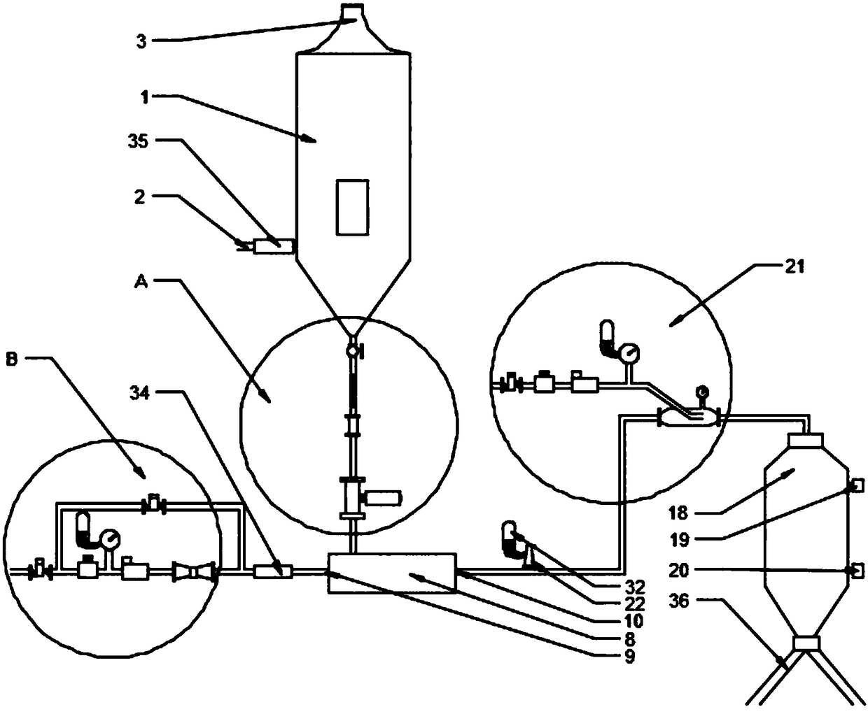
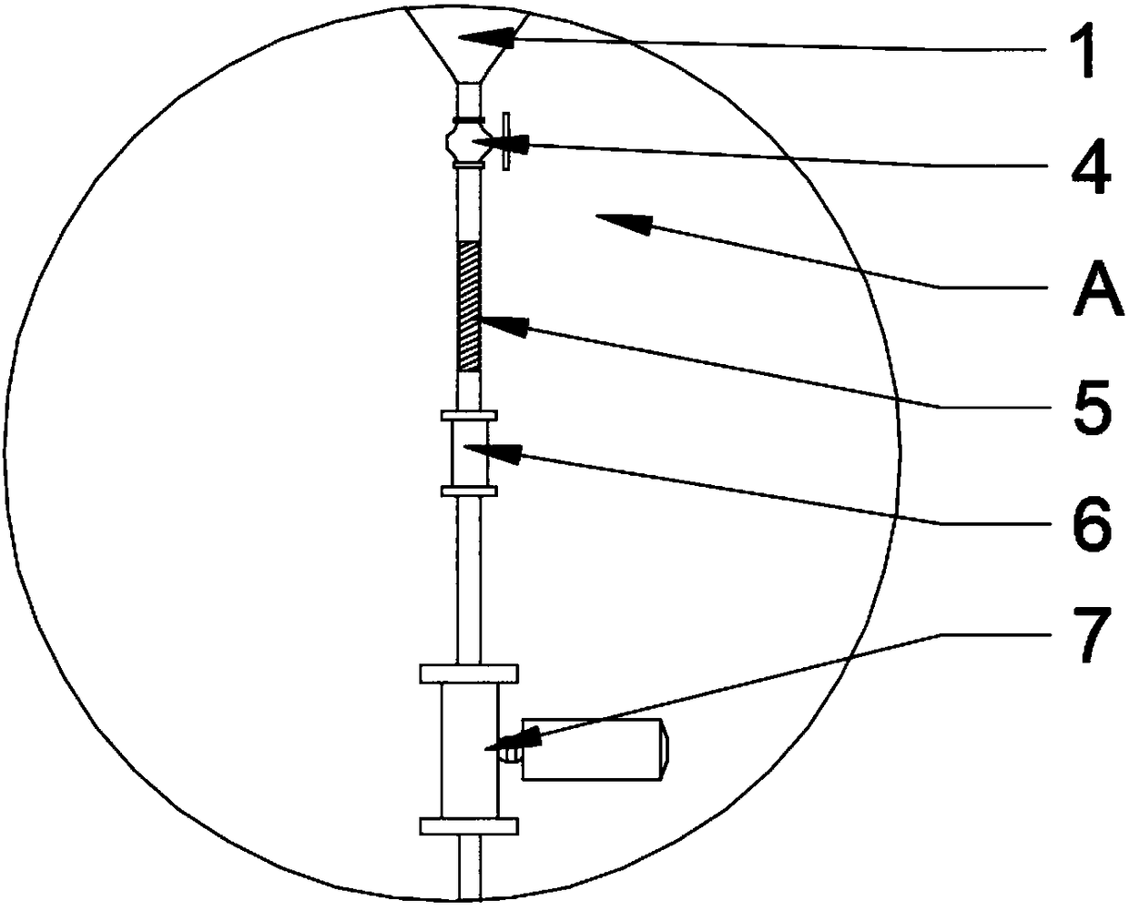
[0017] An energy-saving ultra-long-distance automatic pneumatic conveying system, comprising a drying tower 1, the drying tower 1 is provided with a hot drying air inlet 2, one end of the drying tower 1 is provided with a raw material addition port 3, and the other end of the drying tower 1 is provided with a Electric control ball valve 4, electric control ball valve 4 is connected with bellows 5, bellows 5 is connected with sight mirror 6, sight mirror 6 is connected with electric control rotary valve 7, electric control rotary valve 7 is connected with gas material mixing chamber 8. The upper end of the gas material mixing bin 8 is provided with a raw material bin inlet 9, and the gas material mixing bin 8 communicates with the electronically controlled rotary valve 7 through the raw material bin inlet ( ), and one end of the gas material mixing bin 8 is pro...


PUM


Abstract

The invention discloses an energy-saving extra long distance automatic pneumatic transmission system which comprises a drying tower (1). The drying tower is characterized in that a gas and material mixing cabin (8) communicates in the drying tower (1), a small cabin (18) communicates in the gas and material mixing cabin (8), an air flow anti-blockage device (21) is arranged at the communicating part of the gas and material mixing cabin (8) and the small cabin (18), a speed-up cabin (23) is arranged in the air flow anti-blockage device (21), an L-shaped pipe (26) is arranged in the speed-up cabin (23), an electric control pressure gauge (25) communicates to the speed-up cabin (23), an electric control voltage regulating valve II (28) communicates to the electric control pressure gauge (25),and a dry air inlet II (30) communicates to the electric control voltage regulating valve II (28). Compared with the prior art, the energy-saving extra long distance automatic pneumatic transmissionsystem is high in degree of automation, avoids the blockage problem, and guarantees the relatively high transmission efficiency of raw materials while lowering the power cost.

Description

technical field [0001] The invention relates to the technical field of pneumatic conveying, in particular to an energy-saving ultra-long-distance automatic pneumatic conveying system. Background technique [0002] With the improvement of economic level, the development of industrial technology is getting faster and faster. Pneumatic conveying plays an important role in industrial production. Pneumatic conveying uses the energy of airflow to transport granular materials along the direction of airflow in a closed pipeline, which is a fluid state. A specific application of chemical technology, the pneumatic conveying system is mostly a combination of drying towers, gas material mixing bins, small silos and other parts. It has a simple structure and is easy to operate. During the process, physical operations such as heating, cooling, drying and air classification of materials or certain chemical operations can be carried out at the same time. It has the characteristics of large ...

Claims


Application Information

Patent Timeline
Patent Type & Authority Applications(China)
IPC IPC(8): B65G53/66B65G53/34B65G53/12B65G53/46B65G53/58
CPCB65G53/66B65G53/12B65G53/34B65G53/4608B65G53/58B65G2201/042
Inventor 宋文祥刘虎易关乐何小林邹凯东
Owner SUZHOU LONGJIE SPECIAL FIBER
Why Eureka
Try Eureka