
PLC information transferring method, storage device, PLC and system

A memory and processor technology, applied in general control systems, control/adjustment systems, instruments, etc., can solve the problem of difficult to distinguish PLC or upper computer, low program operation efficiency, process stuck, etc., to improve operation Efficiency and stability, reducing the number of information interactions, and improving device stability

Active Publication Date: 2018-08-14
HUNAN SUNDY SCI & TECH DEV
View PDF6 Cites 2 Cited by
  • Summary
  • Abstract
  • Description
  • Claims
  • Application Information

AI Technical Summary

Problems solved by technology

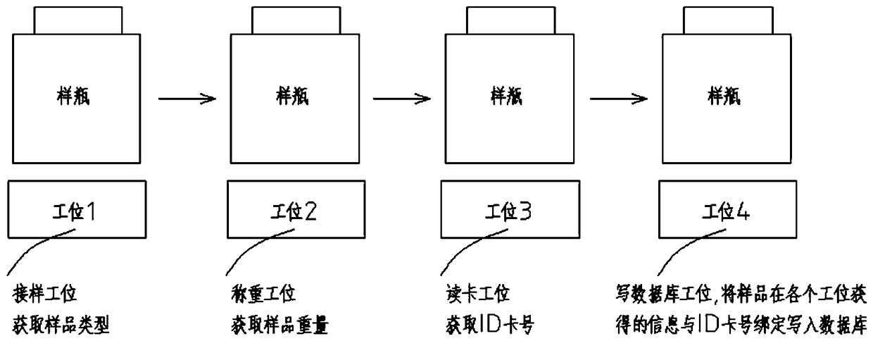
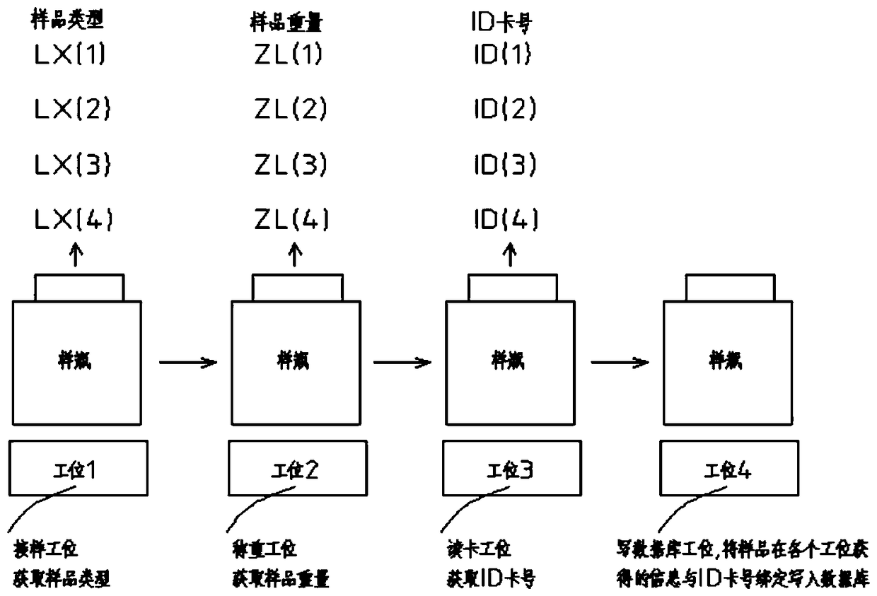
In the actual application process, the following problems are often encountered: Since the automatic sample preparation system often prepares samples continuously, each coal sample has 1-3 full water samples, 1-2 storage and inspection samples, and 1-3 analysis In the same way, there are often several bottles on the bottling line at the same time. In actual situations, it often happens that there are sample bottles from station 1 to station 4.
[0010] 1. The interaction between the PLC and the upper computer is too frequent, and each station has data interaction and response. In practical applications, network interruption, communication abnormality, packet loss and other phenomena often occur, causing the process to be stuck
[0011] 2. The upper computer establishes a queue at each station, and then takes out the corresponding sample data from each station after the capping is successful. The algorithm is more complicated, the program operation efficiency is not high, and queue errors are prone to occur.
[0012] 3. It is difficult to check the cause of the problem: when encountering a problem, it is difficult to distinguish whether it is the problem of the PLC or the problem of the upper computer, and it is also troublesome to check the queue information of each station. This method of sample information transmission with a high degree of coupling When encountering problems, there is often no way to find out

Method used


Image

  • PLC information transferring method, storage device, PLC and system
  • PLC information transferring method, storage device, PLC and system
  • PLC information transferring method, storage device, PLC and system

Examples


Embodiment Construction

[0034] The present invention will be further described below in conjunction with the accompanying drawings and specific preferred embodiments, but the protection scope of the present invention is not limited thereby.

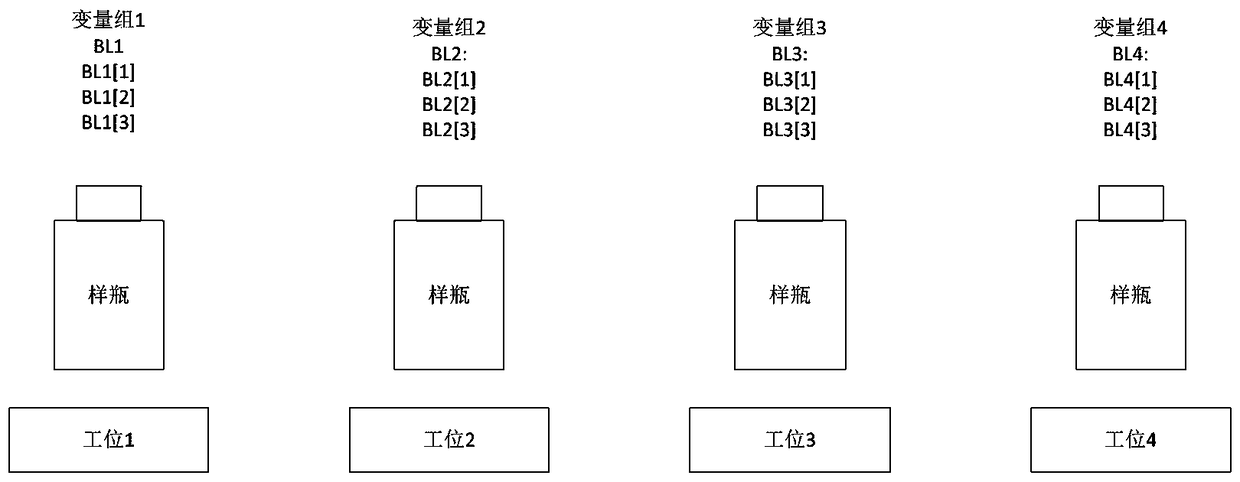
[0035] The LC information transfer method of this embodiment includes the following steps: S1. PLC establishes a variable group for each station; S2. When the station is in operation, write the operation result data into the variable group corresponding to the station; S3 . When the station is transferred to the next station after the operation is completed, the data of the variable group corresponding to the station is assigned to the variable group corresponding to the next station. In this embodiment, step S4 is also included: when the station is the last station, the PLC uploads the data of the variable group corresponding to the station to the host computer.

[0036] In this embodiment, after the station assigns the data of the corresponding variable group ...


PUM


Abstract

The invention discloses a PLC information transferring method, a storage device, a PLC and a system. The method comprises the following steps S1, a variable group is built for each work station via the PLC; S2, when the work station is in operation, operation result data is written in the variable group corresponding to the work station; S3, when the work station is transferred to a next work station via an operation object after the operation ends, data of the variable group corresponding to the work station is assigned to a variable group corresponding to the next work station. The PLC information transferring method is advantageous in that frequency of information interaction between the PLC and a host computer can be effectively reduced, a problem that procedures are stuck due to network interruption, abnormal communication, packet loss and the like can be prevented, program operation efficiency and stability can be improved, and faults can be located and solved conveniently.

Description

technical field [0001] The invention relates to the field of industrial automatic control, in particular to a PLC information transfer method, a memory, a PLC and a system. Background technique [0002] In the industrial automatic control production line, the data information of each station is usually acquired by the PLC, and the acquired data information is uploaded to the host computer and written into the database. However, in the existing control process, the PLC needs to perform multiple data information interactions with the host computer. Take the bottling process of the bottling line of the automatic sample preparation system as an example to illustrate, as follows: figure 1 As shown, in the bottling process, the following situations are often encountered: the sample bottle is sampled at the sample receiving station 1, indicating that all the samples have entered the sample bottle, and the sample type of the bottle of coal sample can be obtained at this station ( ...

Claims


Application Information

Patent Timeline
Patent Type & Authority Applications(China)
IPC IPC(8): G05B19/05
CPCG05B19/054G05B2219/1103
Inventor 谭为陶贤树丁荥中
Owner HUNAN SUNDY SCI & TECH DEV
Learn More