Steel shot tempering device

A technology of tempering device and steel shot, which is applied in the direction of furnace, furnace type, heat treatment equipment, etc., can solve the problems that embrittlement cannot be eliminated, embrittlement is easy to occur, and the comprehensive mechanical properties of steel shot are reduced, so as to achieve better adhesion effect, Avoid the accumulation of silicon powder and save resources

Active Publication Date: 2019-05-28
CHONGQING QINGLAN MACHINERY MFG
View PDF5 Cites 0 Cited by
  • Summary
  • Abstract
  • Description
  • Claims
  • Application Information

AI Technical Summary

Problems solved by technology

However, when the steel shot is tempered in the range of 240-400°C (i.e. low temperature), it is prone to embrittlement, and it is irreversible temper embrittlement. Even if the temperature in the fire chamber rises to 500-650°C (ie high temperature), the embrittlement phenomenon cannot be eliminated, which greatly reduces the comprehensive mechanical properties of the steel shot.

Method used


Image

  • Steel shot tempering device
  • Steel shot tempering device
  • Steel shot tempering device

Examples


Embodiment 1

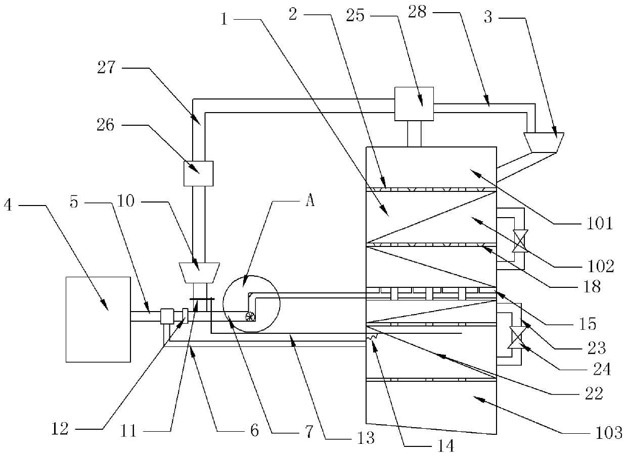
[0026] Example 1, such as figure 1Shown: a steel shot tempering device, including a furnace body 1, inside the furnace body 1 from top to bottom are a feeding chamber 101, two tempering chambers 102 and a collection chamber 103, these chambers pass through four compartments The plates 2 are divided, and each partition 2 is installed horizontally on the inner wall of the furnace body 1 . The upper right side of the furnace body 1 is equipped with a feed hopper 3, the upper end of the feed hopper is in a normally closed state, the feed hopper 3 communicates with the feed chamber 101 of the furnace body 1, and a Hot blast stove 4, the right outer wall of hot blast stove 4 is threadedly connected with a main pipe 5, and the free end of main pipe 5 is equipped with three-way pipe joint, and the bottom of main pipe 5 is provided with the hot-blast pipe 6 that is installed on the three-way pipe joint, and the hot-blast pipe The free end of 6 communicates with the tempering chamber 1...

Embodiment 2

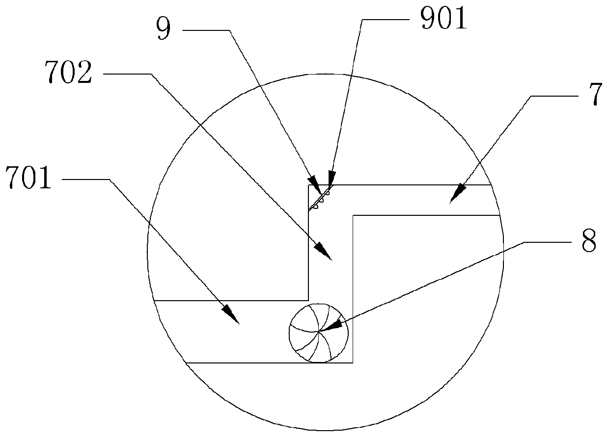
[0028] Embodiment 2 is different from Embodiment 1 in that the shape of the buffer plate 9 is arc-shaped.

[0029] For practical application, refer to figure 1 , when the steel shot is tempered, first the high-temperature and high-pressure gas in the hot blast stove 4 is passed into the main pipe 5, and a part of the hot blast reaches the tempering chamber 102 at the bottom through the hot blast pipe 6. When the pressure reaches the pressure relief valve 24 set When the value is fixed, the tempering chamber 102 at the bottom will release hot air into the tempering chamber 102 on the upper layer, thereby gradually releasing the pressure upwards. Since the corresponding pressure in the pressure relief valve 24 is getting smaller and smaller, each tempering chamber The temperature inside 102 also gradually decreased. Put the quenched steel shot into the feeding hopper 3, the steel shot enters the feeding chamber 101 of the furnace body 1 through the feeding hopper 3, and the ste...


PUM


Abstract

The invention relates to the technical field of steel shot production, and discloses a steel shot tempering device, which includes a tempering mechanism and a temperature adjustment mechanism, and also includes an anti-brittle mechanism. The anti-brittle mechanism includes an induced draft fan and a silicon feed hopper equipped with a silicon feed valve , there is a silicon inlet pipe connected between the hot blast stove and the tempering chamber in the middle layer, and the silicon inlet hopper is installed on the silicon inlet pipe; a dispersing plate is installed in the tempering chamber in the middle layer, and a second transmission plate corresponding to the partition is installed on the dispersing plate. The dispersing plate is provided with a plurality of dispersing holes vertically, and the dispersing plate is provided with a dispersing channel horizontally. The bottom of the dispersing hole communicates with the dispersing channel, and one side of the dispersing channel communicates with the silicon inlet pipe. The partition above the dispersing plate There are through holes on both sides; one side of the induced draft fan is connected to the feed chamber through the recovery pipe, and the other side of the induced fan is connected to the silicon feeding hopper through the silicon return pipe, and the first cooler is installed on the silicon return pipe. The invention can solve the problem of low-temperature tempering embrittlement of the existing steel shot, and improve the performance and quality of the steel shot.

Description

technical field [0001] The invention relates to the technical field of steel shot production, in particular to a steel shot tempering device. Background technique [0002] Steel shot is a kind of spherical particle made of special material through special heat treatment. In the process of steel shot preparation, the equipment generally used is a centrifuge, which melts the high-carbon steel and pours it into a rotating centrifugal plate, and then relies on the centrifugal force of the centrifuge to throw out various sizes of shot bodies. The shot body will fall into the quenching pool for rapid cooling, and the steel shot after rapid cooling will be reheated and tempered, and the steel shot will reach the required hardness. Among them, in the tempering process, the steel shot generally adopts a high-temperature tempering process, the purpose of which is to make the steel shot have better strength, plasticity and toughness, so as to facilitate the steel shot to meet the use ...

Claims


Application Information

Patent Timeline
Patent Type & Authority Patents(China)
IPC IPC(8): C21D9/36C21D1/70
CPCC21D1/70C21D9/36
Inventor 苏亚君
Owner CHONGQING QINGLAN MACHINERY MFG
Why Eureka
Try Eureka