
Hydroelectric generating set efficiency testing device and optimized measuring method thereof

A technology for hydropower unit and efficiency test, applied in the field of hydraulic turbines, can solve the problems of long water diversion pipeline, prone to fracture or accident, temperature loss, etc., to achieve the effect of improving strength and safety, reducing the number of sensors, and expanding the scope of application

Active Publication Date: 2018-08-17
CHINA INST OF WATER RESOURCES & HYDROPOWER RES
View PDF6 Cites 0 Cited by
  • Summary
  • Abstract
  • Description
  • Claims
  • Application Information

AI Technical Summary

Problems solved by technology

[0019] 2. Insulation of the water diversion pipe of the water intake container on the high pressure side
[0020] Although the temperature-measuring container is insulated with heat-insulating materials, the connecting section between the temperature-measuring container and the volute, that is, the flow measuring device-electromagnetic flowmeter is installed on the water diversion pipeline, and there is no heat-insulating measure, which causes water to flow into the measuring chamber through the flowmeter. Before the thermostat, a large amount of heat energy loss has occurred
[0021] In addition, according to the regulations of GB / T5321-2005 (Appendix AA.1), the electromagnetic flowmeter needs to meet the measurement requirements of the first 10 times the pipe diameter and the last 5 times the pipe diameter, so the water diversion pipeline needs to be quite long, resulting in additional temperature loss, and the increase in the length of the water diversion pipeline will also cause the quality of the entire water diversion container to be all pressed on the connecting flange between the container and the electromagnetic flowmeter, which is prone to breakage or accidents
[0022] 3. The insulation problem of the low-pressure side insulation measurement container
However, the low-pressure measurement section of the turbine, that is, the tail water outlet diffusion section is far away from the high-pressure side, that is, the inlet of the volute. If it is necessary to introduce the low-pressure side water flow into the thermal insulation measurement container, it is quite difficult to heat and insulate the outlet pipe. For closed tail water For the cross section, special pipes and holes need to be dug in the concrete layer to extract the water flow, and it is basically impossible to achieve heat insulation; for the open tail water section, the pipes for the water flow will be in long-distance contact with the air, which will also cause serious heat loss
It is difficult to achieve thermal insulation by burying steel pipes in concrete to divert water
[0024] 4. The low-pressure side uses a heat-insulating measuring container with a single water intake, which cannot meet the requirements of the regulations
[0026] However, with the low-pressure side insulation measuring container of the invention, a single water intake cannot meet the accuracy requirements of multiple measurement points, and it is impossible to compare the efficiency of each measurement point

Method used


Image

  • Hydroelectric generating set efficiency testing device and optimized measuring method thereof
  • Hydroelectric generating set efficiency testing device and optimized measuring method thereof
  • Hydroelectric generating set efficiency testing device and optimized measuring method thereof

Examples


Embodiment Construction

[0088] In order to make the object, technical solution and advantages of the present invention clearer, the present invention will be described in further detail below with reference to the accompanying drawings and examples.

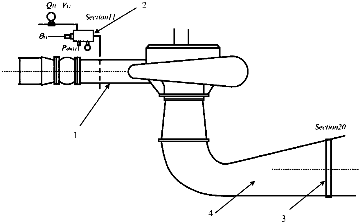
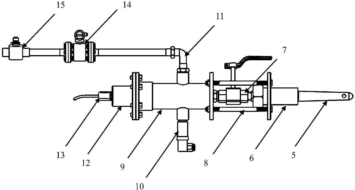
[0089] Such as figure 1 As shown, a hydroelectric unit efficiency test device includes: a water turbine, a high-pressure side pipeline 1 , a low-pressure side pipeline 4 , a high-pressure measuring device 2 and a low-pressure measuring device 3 .

[0090] Both ends of the water turbine are respectively connected to a high-pressure side pipeline 1 and a low-pressure side pipeline 4 .

[0091] The high-pressure measuring device 2 takes water from the high-pressure side pipeline 1, and then performs parameter measurement on the sampled water flow.

[0092] The low-pressure measuring device 3 is installed in the low-pressure side pipeline 4 to directly measure the pressure and temperature parameters of the main water flow in the water flow.

[0093] Such ...


PUM


Abstract

The invention discloses a hydroelectric generating set efficiency testing device and an optimized measuring method thereof. The hydroelectric generating set efficiency testing device is composed of ahigh-pressure measuring device and a low-pressure measuring device. The high-pressure measuring device takes water from a high-pressure side and carries out parameter measurement on a sampled water flow. The low-pressure measuring device installed at a low-pressure side is used for measuring pressure and temperature parameters of a main water flow in a water flow directly. Besides, the optimized measuring method includes: carrying out measuring and calculating to obtain a preliminary flow; iteratively calculating an actual flow; carrying out multi-time iterative calculation to obtain a final flow; and calculating hydroelectric generating set efficiency. The hydroelectric generating set efficiency testing device and the optimized measuring method thereof have the following advantages: the application range of the thermodynamic method is extended; a problem of difficult heat insulation caused by the water diversion container utilization is solved; the requirement of the number of measuring points is met; testing requirements of a closed measuring fracture surface and an opening measuring fracture surface are met simultaneously; each measuring point can be measured, calculated, and compared independently; and the testing precision is improved.

Description

technical field [0001] The invention relates to the technical field of water turbines, in particular to a hydroelectric unit efficiency test device and an optimization measurement method. Background technique [0002] Turbine efficiency is one of the important technical indicators of hydropower stations, especially in the acceptance and transfer process of international projects, turbine efficiency indicators play an important role, so most of them require the absolute efficiency test of turbines. The difficulty in measuring the efficiency of water turbines lies in the measurement of absolute flow. For water turbines (including energy storage pumps and pump turbines), according to the measurement methods of flow parameters, they can be divided into flow meter method, pressure time method, ultrasonic method and thermodynamic method. The three methods are to directly measure the absolute flow of the unit, and then calculate the efficiency. [0003] According to "IEC60041-1991...

Claims


Application Information

Patent Timeline
Patent Type & Authority Applications(China)
IPC IPC(8): G01R31/34
CPCG01R31/343
Inventor 周叶潘罗平曹登峰刘永强余江成程大勇李立罡谭志锋
Owner CHINA INST OF WATER RESOURCES & HYDROPOWER RES
Learn More