
Production system for utilizing solid waste to produce thermal insulation building blocks or composite wall slabs

A technology for thermal insulation blocks and composite wall panels, which is applied in manufacturing tools, ceramic molding workshops, ceramic molding machines, etc., can solve the problems of poor sound insulation, low production efficiency, and high energy consumption in the production process.

Inactive Publication Date: 2018-08-21
金畅
View PDF0 Cites 3 Cited by
  • Summary
  • Abstract
  • Description
  • Claims
  • Application Information

AI Technical Summary

Problems solved by technology

Composite wall panels and roof panels of prefabricated buildings at home and abroad are produced by mold prefabrication process, extrusion process, etc. The disadvantage is that the mold prefabrication process cannot meet the architectural design requirements. , Molds, templates, brackets, etc. need to be replaced, resulting in reinvestment of equipment funds and a large number of idle production equipment, increasing product costs; more production links, more labor, high labor intensity, and low production efficiency
GRC wall panels and EPC wall panels produced by extrusion technology are used as exterior walls because they cannot meet the requirements of building energy conservation, so they need to be used as external wall insulation systems; exterior wall panels and decorative materials cannot be formed at one time, which increases the amount of work and prolongs the construction The construction period increases the construction cost; the sound insulation effect is poor; the wall panels produced by the above two wall panel production processes need high temperature, high pressure, and steam curing, and the production process consumes a lot of energy, which does not meet the requirements of low-carbon economic development advocated by the state

Method used


Image

  • Production system for utilizing solid waste to produce thermal insulation building blocks or composite wall slabs
  • Production system for utilizing solid waste to produce thermal insulation building blocks or composite wall slabs
  • Production system for utilizing solid waste to produce thermal insulation building blocks or composite wall slabs

Examples


Embodiment 1

[0075] Such as Figure 1-4 As shown, the production system using solid waste residues to manufacture thermal insulation blocks or composite wallboards includes a spraying release agent area 5, a production area, a steam curing area, a post-treatment area 28, and a transmission device running through each area, which are arranged sequentially from front to back;

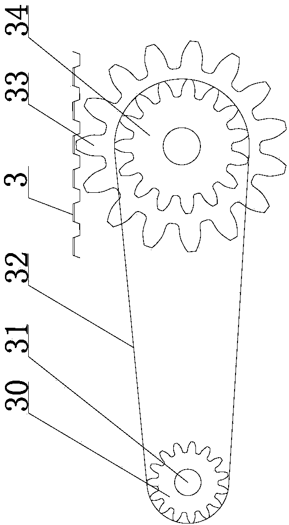
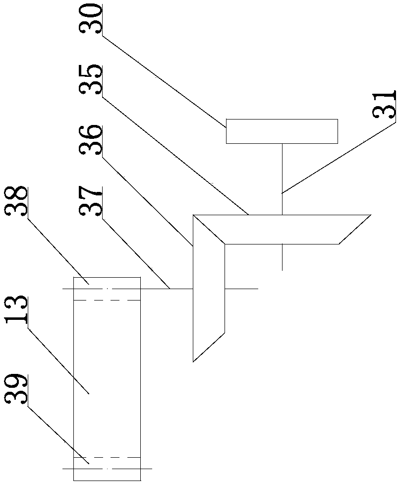
[0076] The transmission device comprises a sprocket chain plate conveying device and a lower belt 4, the sprocket chain plate conveying device comprises a driving sprocket 25, a chain plate 3 and a driven sprocket 2, and the driving sprocket 25 and the driven sprocket 2 are installed in a fixed position. On the bracket 1, the driving sprocket 25 is driven by the driving device, the driven sprocket 2 is linked with the driving sprocket 25 through the chain plate 3, and the lower belt 4 is attached to the outer periphery of the chain plate 3;

[0077] A spraying release agent device 6 is set in the spray release agent a...

Embodiment 2

[0094] The structure of this production system and the process of producing panels are roughly the same as those of Embodiment 1, except that: the spraying release agent area 5, the outer surface production area 7, the outer leaf plate production area 17, and the lower insulation board filling area 19 The shaping belts 13 on both sides are flat belts, and the shaping belts 13 on both sides of the middle leaf plate production area 20, the upper insulation plate filling area 21, the inner leaf plate production area 22, the interior surface production area 23, and the pre-steaming area 24 are convex surfaces belts (such as Figure 10 shown), the lower belt 4 attached to the chain plate 3 is a belt with convex surfaces on both sides (such as Figure 6 shown), or a flat belt, and the pressure roller 16 in the outer surface production area 7 and the outer leaf plate production area 17 is a pressure roller with concave surfaces at both ends (such as Figure 11 shown), or flat roller...

Embodiment 3

[0097] The structure of this production system and the second embodiment and the process of producing panels are roughly the same, the difference is that there is no interior surface production area 23 in the production area; spraying release agent area 5, exterior surface production area 7, and outer leaf plate production The shaping belts 13 on both sides of the area 17 and the lower insulation board filling area 19 are plane belts, the middle blade production area 20, the upper insulation board filling area 21, the inner blade production area 22, and the two sides of the steam curing front area 24. The shaping belt 13 For belts with raised surfaces (such as Figure 10 shown), the lower belt 4 attached to the chain plate 3 is a belt with convex surfaces on both sides (such as Figure 6 shown), or a flat belt, and the pressure roller 16 in the outer surface production area 7 and the outer leaf plate production area 17 is a pressure roller with concave surfaces at both ends (s...


PUM


Abstract

The invention relates to a production system for utilizing solid waste to produce thermal insulation building blocks or composite wall slabs, which comprises a release agent spraying area, a production area, a steam curing area, a post-processing area and a conveyer running through all the areas, that are sequentially arranged from the front to the rear; the conveyer comprises a chain wheel-link plate transporter and a lower belt, and the lower belt is attached to the periphery of link plates of the chain wheel-link plate transporter; a release agent sprayer is arranged in the release agent spraying area; shaping mechanisms which are perpendicular to the link plates are arranged on two sides of the release agent spraying area and the production area, belt drive mechanisms are adopted by the shaping mechanisms, belts in the belt drive mechanisms are shaping belts, and the shaping belts are synchronous with the lower belt on the periphery of the link plates. The production system can increase the quality of the thermal insulation building blocks or slabs, the efficiency of production and the building assembly rate and reduce building cost.

Description

technical field [0001] The invention relates to a production system for making thermal insulation blocks or composite wallboards by using solid waste residue, which is used for preparing thermal insulation blocks or composite wallboards. Background technique [0002] The stockpiling of solid waste residues (water slag, steel slag, fly ash, red mud, tailings slag, etc.) occupies a large amount of cultivated land and produces smog when it encounters wind, and pollutes groundwater sources when it encounters rain and snow, causing serious harm to the ecological environment and affecting people's production. Lives are seriously affected. The use of solid waste residues to produce building materials not only saves resources, protects cultivated land, and maintains the ecological environment, but also enables comprehensive utilization of resources, turning waste into wealth, and turning harm into profit. [0003] At present, the whole country is vigorously promoting prefabricated ...

Claims


Application Information

Patent Timeline
IPC IPC(8): B28B15/00B28B5/02
CPCB28B15/00B28B5/02
Inventor 金畅
Owner 金畅
Learn More