Optical fiber laser output device

An output device, fiber laser technology, applied in the direction of lasers, laser parts, laser parts, etc., can solve the problems of unfavorable fiber laser output device volume and weight control, achieve volume and weight control, accelerate heat export, improve The effect of portability

Pending Publication Date: 2018-08-21
SHENZHEN JPT OPTO ELECTRONICS CO LTD
View PDF8 Cites 2 Cited by
  • Summary
  • Abstract
  • Description
  • Claims
  • Application Information

AI Technical Summary

Problems solved by technology

However, in special application fields, such as outdoor high-voltage line obstacle removal, etc., it is necessary to use hundreds of watt-level optical lasers and require portability, and more stringent requirements are placed on the volume and weight control of fiber laser output equipment. The existing high-power The output fiber laser output device is generally cooled by water cooling to ensure heat dissipation efficiency, and then includes a water-cooled plate and a water cooler in the structure, which is not conducive to the volume and weight control of the high-power output fiber laser output device

Method used


Image

  • Optical fiber laser output device
  • Optical fiber laser output device
  • Optical fiber laser output device

Examples


Embodiment Construction

[0027] In order to facilitate the understanding of the present invention, the following will describe the present invention more fully. However, the present invention can be embodied in many different forms and is not limited to the embodiments described herein. On the contrary, these embodiments are provided to make the understanding of the disclosure of the present invention more thorough and comprehensive.

[0028] Unless otherwise defined, all technical and scientific terms used herein have the same meaning as commonly understood by one of ordinary skill in the technical field of the invention. The terms used herein in the description of the present invention are for the purpose of describing specific embodiments only, and are not intended to limit the present invention.

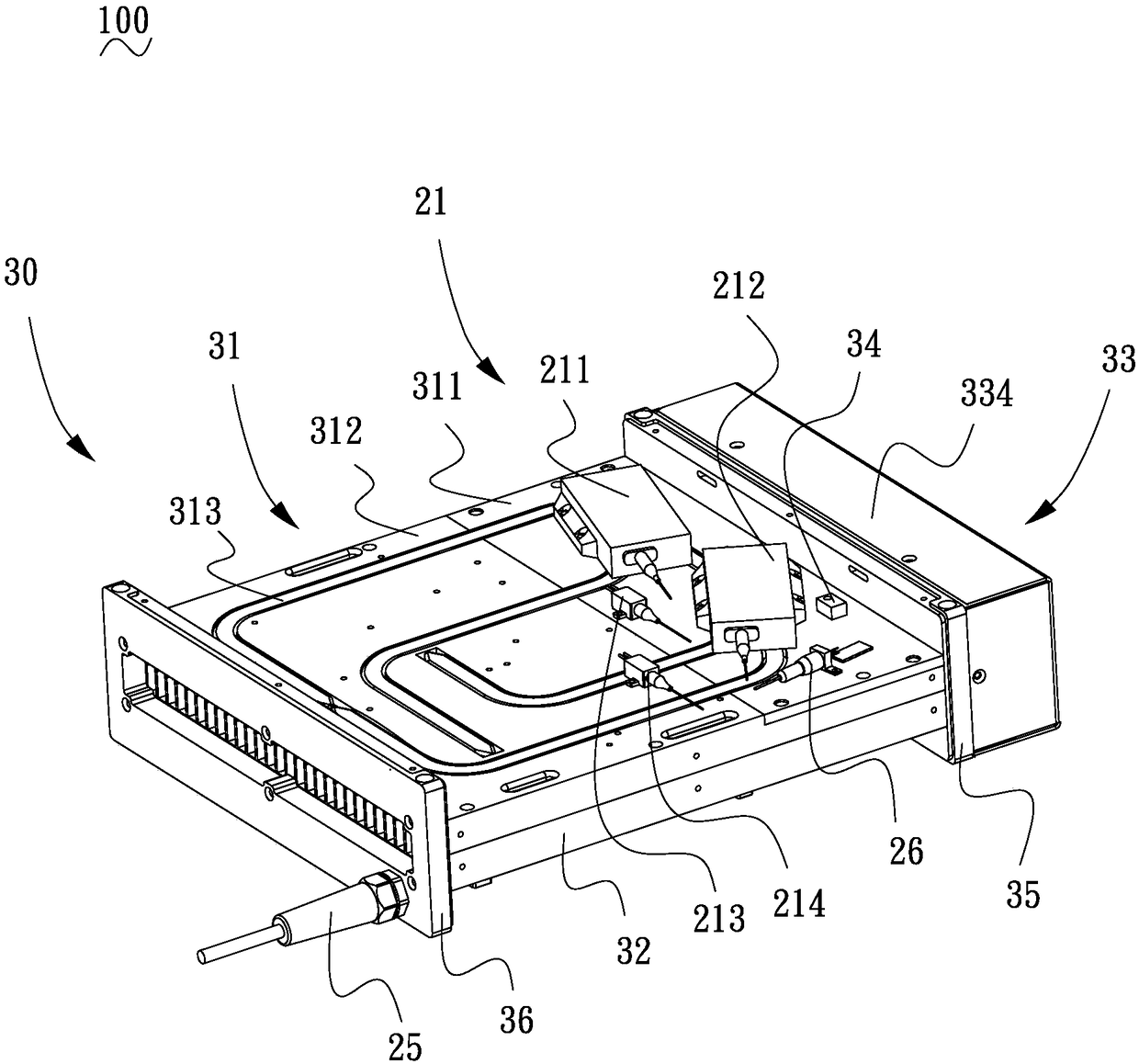
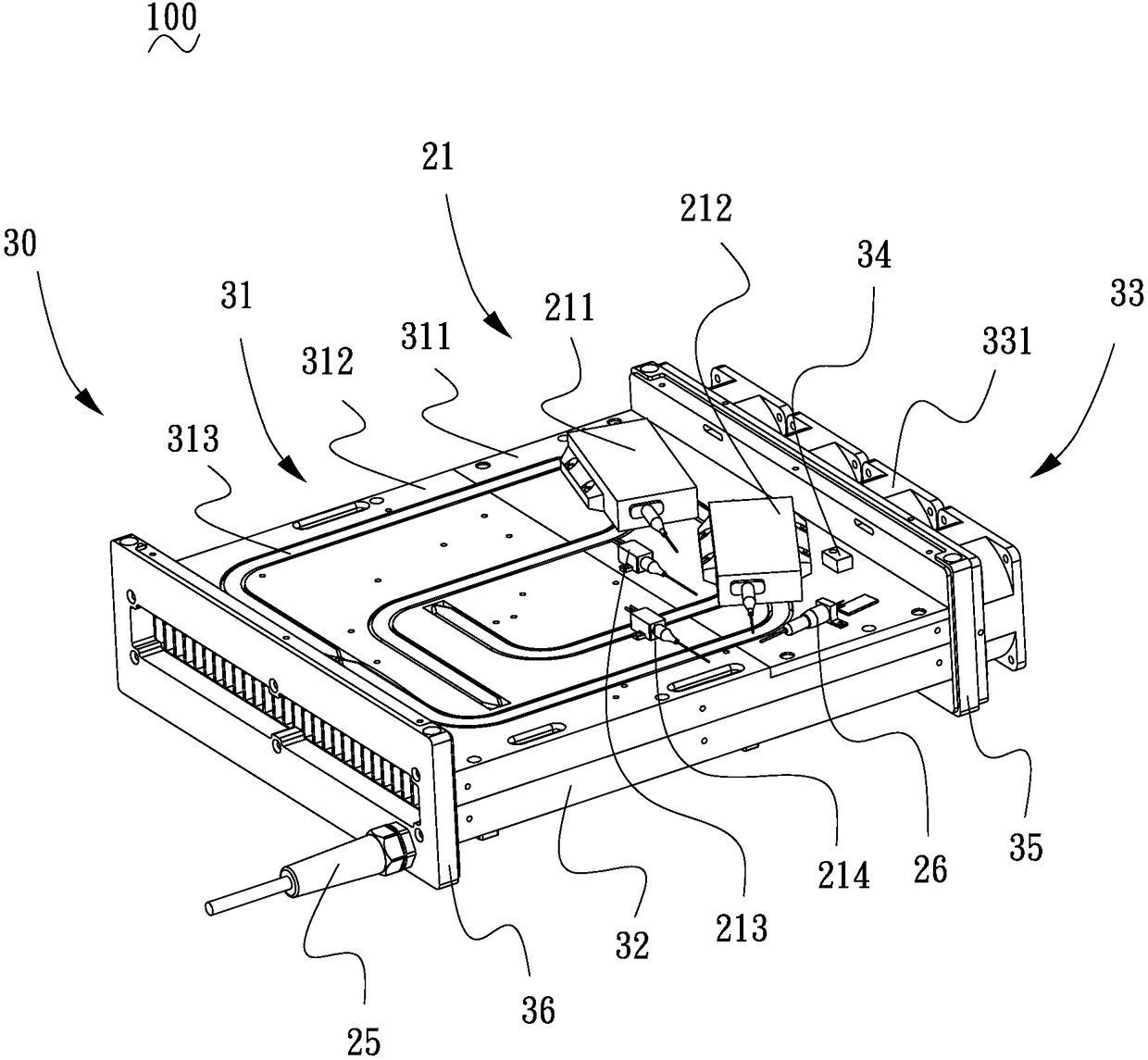
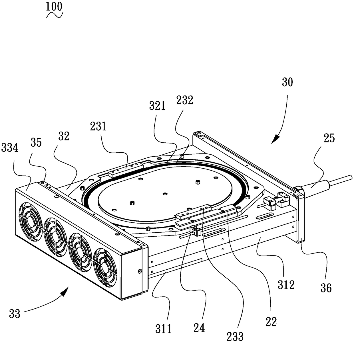
[0029] see Figure 1 to Figure 7 , is a fiber laser output device 100 according to a preferred embodiment of the present invention, which is used to output laser light. The fiber laser output device 1...


PUM


Abstract

The invention relates to an optical fiber laser output device, which comprises: a light source generating mechanism, wherein the light source generating mechanism comprises a pumping source component,a pumping combiner, an optical fiber resonant cavity, a cladding power stripper and a collimating output device; a heat dissipation mechanism, wherein the heat dissipation mechanism comprises a firstradiator, a second radiator and a gas flow generating component; the pumping source component is mounted on the first radiator; the first radiator comprises a copper substrate, an aluminum substrateconnected with the copper substrate, and a plurality of heat pipes; the heat pipe comprises an evaporation section and a condensation section. The evaporation section of the heat pipe is welded on theupper surface of the copper substrate, and the condensation section of the heat pipe is welded on the upper surface of the aluminum substrate. The pumping source component is cooled by the first radiator. The heat pipe dissipates part of the heat on the copper substrate to the aluminum substrate through the first radiator. The gas flow generating component drives the gas between the first radiator and the second radiator to flow, so that the heat dissipation efficiency is ensured while the heat dissipation structure is simplified, the volume and the weight of the fiber laser output device areeffectively controlled, and the portability is improved.

Description

technical field [0001] The invention relates to laser technology, in particular to a fiber laser output device. Background technique [0002] Fiber laser output equipment has the advantages of small size, light weight, compact and flexible structure, adjustment-free, maintenance-free, and high stability. It can work in harsh environments, that is, it has high resistance to dust, vibration, shock, humidity and temperature. The tolerance is unmatched by traditional lasers. However, in special application fields, such as outdoor high-voltage line obstacle removal, etc., it is necessary to use hundreds of watt-level optical lasers and require portability, and more stringent requirements are placed on the volume and weight control of fiber laser output equipment. The existing high-power The output fiber laser output device is generally cooled by water cooling to ensure heat dissipation efficiency, and then includes a water-cooled plate and a water cooler in the structure, which ...

Claims


Application Information

Patent Timeline
IPC IPC(8): H01S3/04H01S3/042
CPCH01S3/0404H01S3/0405H01S3/042
Inventor 苏鑫达强瑞荣熊钊颀朱江杰
Owner SHENZHEN JPT OPTO ELECTRONICS CO LTD
Why Eureka
Try Eureka