Additive manufacturing device and method

A technology of additive manufacturing and cathode, which is applied in the field of additive manufacturing, can solve problems such as beam spot quality degradation, and achieve the effects of improving quality, increasing life, and facilitating manufacturing and maintenance

Pending Publication Date: 2018-08-24
QUICKBEAM CO LTD
View PDF0 Cites 4 Cited by
  • Summary
  • Abstract
  • Description
  • Claims
  • Application Information

AI Technical Summary

Problems solved by technology

[0005] The purpose of the present invention is to provide an additive manufacturing device and an additive manufac

Method used


Image

  • Additive manufacturing device and method
  • Additive manufacturing device and method
  • Additive manufacturing device and method

Examples


Embodiment 1

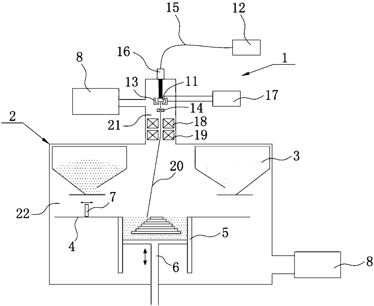
[0042] This embodiment provides an additive manufacturing device, such as figure 1 As shown, the additive manufacturing device includes a ray generating device 1, a forming chamber 2, a hopper 3, a powder spreading platform 4, a forming cylinder 5, a piston 6 and a scraper 7, wherein:

[0043] The above-mentioned ray generating device 1 is arranged on the top of the forming chamber 2, and at least one of the above-mentioned hoppers 3 is arranged in the forming chamber 2. In this embodiment, two hoppers 3 are arranged symmetrically on the left and right sides of the forming chamber 2. , the powder material is housed in the hopper 3 . The above-mentioned powder spreading platform 4 is provided below the hopper 3 , and the powder material in the hopper 3 can be transported onto the powder spreading platform 4 . A forming cylinder 5 is arranged on the powder spreading platform 4, and a piston 6 which can move up and down is arranged in the forming cylinder 5. A movable scraper 7...

Embodiment 2

[0080] The difference between the additive manufacturing device of this embodiment and the first embodiment is that the additive manufacturing device of this embodiment is a wire-feeding type, rather than the powder-spreading structure described in the first embodiment.

[0081] In this example, refer to Figure 5 , the additive manufacturing device includes a ray generating device 1 and a fuse tray 9, on which a fuse 10 is arranged, and the electron beam 20 formed by the above-mentioned ray generating device 1 will be on the formed part of the three-dimensional part To form a molten pool, specifically, the formed part of a three-dimensional part is placed on a mobile platform with at least three degrees of freedom of movement, X, Y, and Z. A molten pool is formed on it.

[0082] Afterwards, the fuse 10 is transported through the fuse tray 9, so that the fuse 10 is filled into the molten pool, and is heated and melted by the electron beam 20 to accumulate, and the three-dimen...


PUM

PropertyMeasurementUnit
Outer diameteraaaaaaaaaa

Abstract

The invention belongs to the technical field of additive manufacturing, and discloses an additive manufacturing device and method. The additive manufacturing device comprises a ray generating device.The ray generating device comprises a cathode, a laser, a grid electrode and an anode. Electrons can escape after the cathode is heated. The laser is used for generating lasers, and the lasers are used for heating the cathode. The grid electrode is used for collecting the electrons to form an electron beam. The anode is located below the cathode and arranged in a ground connection mode, a hole isformed in the middle of the anode, and a potential difference which is used for enabling the electron beam to pass through the hole is formed between the anode and the cathode. According to the additive manufacturing device and method, the lasers are generated by the laser, the cathode is heated by the lasers, the cathode can generate the electrons, the electron beam can be formed, and therefore compared with the mode of electric heating of a cathode in the prior art, the additive manufacturing device and method have the advantages that high-current heating is not required, the phenomenon thatdue to the fact that a magnetic field is generated by current, distribution of the electrons can be affected is avoided, the life of the cathode is prolonged, the quality of beam spots in the additive manufacturing process is improved, and the quality and the efficiency of additive manufacturing are also improved.

Description

technical field [0001] The invention relates to the technical field of additive manufacturing, in particular to an additive manufacturing device and an additive manufacturing method. Background technique [0002] Additive manufacturing (3D printing) is a manufacturing technique that creates three-dimensional solid parts by continuously fusing more than one thin layer of material. At present, additive manufacturing can use electron beams as heat sources, which can heat thin layers of materials to very high temperatures (500-1000 degrees Celsius), with low stress during the forming process and low risk of cracking; they can be used directly without heat treatment after forming. [0003] Current electron beam sources generally use electric heating or primary electron bombardment to heat the cathode, so that the temperature of the cathode rises to a temperature where electrons can overflow, and then an electron beam is generated to heat and shape the thin layer of material. Amo...

Claims


Application Information

Patent Timeline
IPC IPC(8): B29C64/393B22F3/105B33Y30/00B33Y10/00
CPCB22F3/105B29C64/393B33Y10/00B33Y30/00Y02P10/25
Inventor 郭超马旭龙
Owner QUICKBEAM CO LTD
Why Eureka
Try Eureka