Amplitude and phase error correction method of mimo radar transceiver array based on clutter

An array amplitude and phase error, radar transceiver technology, applied in the radar field, can solve problems such as large amount of calculation, non-unique array error estimation, and inapplicability to large error estimation, etc., and achieves the effect of small amount of calculation and low complexity

Active Publication Date: 2021-07-20
XIDIAN UNIV
View PDF7 Cites 0 Cited by
  • Summary
  • Abstract
  • Description
  • Claims
  • Application Information

AI Technical Summary

Problems solved by technology

The current self-correction algorithms mainly include the following: Weiss and Friedlander proposed an array error correction algorithm using the likelihood function as a cost function, but because the algorithm needs to perform a first-order Taylor expansion on the array flow, it is not suitable for large errors estimate
In order to solve the problem of slow convergence of the cost function of the self-correction algorithm, a fast-converging array error correction method was proposed, which uses the SAGE algorithm to solve the maximum likelihood estimation problem
In addition, Paulraj and Kailath proposed an array error correction method that uses the special structure of the data to achieve fast convergence. This method uses the Toeplitz property of the signal covariance matrix to correct the amplitude and phase errors, but this method is only applicable to uniform linear arrays. Arrays with special structures, such as arrays, are limited in practical application scenarios
[0006] The existing self-calibration methods are mostly based on passive receiving arrays, which often require an accurately known number of targets, and the signal-to-noise ratio of the target echo has a great influence on the estimation accuracy. real-time processing
In addition, when the array is an equidistant uniform linear array, since the number of unknowns is 1 more than the number of known equations and usually cannot be effectively separated and decoupled, there is a possibility that the array error estimation is not unique

Method used


Image

  • Amplitude and phase error correction method of mimo radar transceiver array based on clutter
  • Amplitude and phase error correction method of mimo radar transceiver array based on clutter
  • Amplitude and phase error correction method of mimo radar transceiver array based on clutter

Examples


Embodiment 1

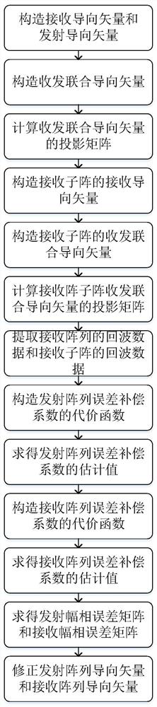
[0038] The amplitude error and phase error of the array are inevitable errors in array signal processing. When there are amplitude and phase errors, it will cause the mismatch of the array, which will lead to the degradation of spatial spectrum estimation and digital beamforming performance. The traditional amplitude and phase error correction method requires certain preconditions, such as accurately knowing the number of targets, and the samples need to be independent and identically distributed. These preconditions are often difficult to meet in actual situations. In order to solve the above problems, the present invention proposes a method based on heterogeneous Wave MIMO radar transceiver array amplitude and phase error correction method, see figure 1 , including the following steps:

[0039] First, it is assumed that the MIMO radar is an equidistant linear array for transmitting and receiving. It is assumed that the distance between the transmitting and receiving arrays i...

Embodiment 2

[0075] Based on the clutter MIMO radar transceiver array phase error correction method is the same as embodiment 1, the projection matrix of the calculation transceiver joint steering vector described in step (3), is specifically calculated by the following formula:

[0076] (3a) Evenly divide the azimuth interval [-π / 2 π / 2] into K parts, K>>N t N r , Construct the joint steering matrix A of sending and receiving V :

[0077]

[0078] Among them, K is the number of azimuth divisions, θ i (i=1,2,...,K) is the azimuth, N t is the number of transmitting array elements, N r is the number of receiving elements.

[0079] (3b) Calculate its projection matrix P ⊥

[0080]

[0081] in, Indicates that the dimension is N t N r ×N t N r The identity matrix of A V is the sending and receiving joint steering matrix, [·] T Indicates the transpose, [·] -1 Indicates inversion.

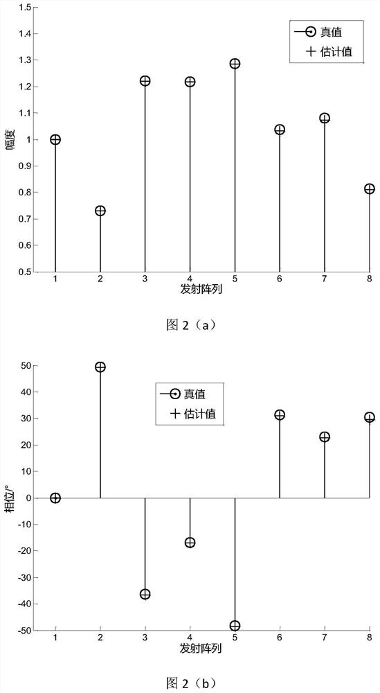
[0082] In this example, the number of transmitting array elements of the radar is 6, and the ...

Embodiment 3

[0085] Based on the clutter MIMO radar transceiver array amplitude and phase error correction method is the same as embodiment 1-2, the calculation of the projection matrix of the receiving sub-array transceiver joint steering vector described in step (6), specifically calculated by the following formula:

[0086] (6a) Evenly divide the azimuth interval [-π / 2 π / 2] into K parts, K>>N t P r , Construct the joint steering matrix A of sending and receiving sub :

[0087]

[0088] Among them, K is the number of azimuth divisions, θ i (i=1,2,...,K) is the azimuth, N t is the number of transmitting array elements, p r The number of elements calibrated for the receiving array.

[0089] (6b) Calculate its projection matrix

[0090]

[0091] in, for dimension N t P r ×N t P r The identity matrix of [·] T Indicates the transpose, [·] -1 Indicates inversion.

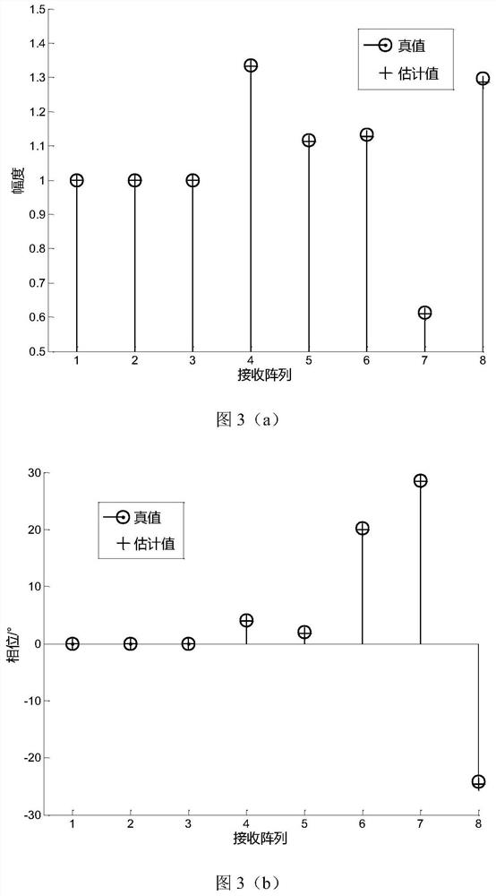
[0092] In this example, the number of radar transmitting array elements is 10, the number of radar receivin...


PUM


Abstract

The invention discloses a clutter-based MIMO radar transceiver array amplitude and phase error correction method, which mainly solves the problem that the radar detection performance decreases due to the inconsistency of the array element amplitude and phase. The realization process includes: constructing the receiving, transmitting and transmitting and receiving joint steering vectors of the radar and the receiving and transmitting joint steering vectors of the radar receiving sub-array; respectively calculating the projection matrix of the receiving and transmitting joint steering vectors of the radar and the radar receiving sub-array; using the projection matrix and echo data respectively to construct the cost function of transmitting and receiving array error compensation coefficients and find the optimal solution of each cost function; use the transmitting and receiving array amplitude and phase error matrix to correct the transmitting and receiving array steering vectors to realize the radar transmitting and receiving array amplitude and phase error correction. The invention does not need to estimate the number of signal sources and targets, and only needs a single echo sample to effectively estimate the amplitude and phase error of the MIMO radar transceiver array, with small calculation amount and low complexity, and is suitable for real-time processing of MIMO radar transceiver array error correction.

Description

technical field [0001] The invention belongs to the technical field of radar, and mainly relates to spatial spectrum estimation and digital beam forming, in particular to a clutter-based amplitude-phase error correction method of MIMO radar transceiver arrays, which can be used for amplitude-phase error correction of MIMO radar transmitting arrays and receiving arrays. Background technique [0002] Multiple-input multiple-output MIMO radar, as a new radar system, has received extensive attention in recent years. Its biggest feature is to radiate different signals through multiple transmitting antennas, and to separate, decouple and coherently combine the echoes of multiple receiving antennas. Because MIMO radar has the advantage of waveform diversity, it has better performance than traditional phased array radar in terms of target angle estimation, detection and tracking, and clutter suppression. However, in practical engineering applications, it is difficult to guarantee th...

Claims


Application Information

Patent Timeline
Patent Type & Authority Patents(China)
IPC IPC(8): G01S7/40
CPCG01S7/40G01S7/4004
Inventor 纠博高雨婷刘源刘宏伟周生华
Owner XIDIAN UNIV
Why Eureka
Try Eureka