
Interruption control flow diagram-based interruption verification method

A technology of control flow graph and verification method, applied in the direction of instrument, error detection/correction, calculation, etc., can solve problems such as affecting security, randomness and complexity of interrupt handler, and achieve the effect of improving reliability and security

Active Publication Date: 2018-08-28
EAST CHINA NORMAL UNIVERSITY +1
View PDF2 Cites 4 Cited by
  • Summary
  • Abstract
  • Description
  • Claims
  • Application Information

AI Technical Summary

Problems solved by technology

However, there are usually a large number of different interrupt sources (sources that signal interrupt requests) in an interrupt driver, and even most real-time systems support nested interrupts in interrupt handlers, through which an interrupt can be assigned a higher priority These situations lead to the same randomness and complexity of the interrupt handler
In addition, due to the introduction of the interrupt mechanism, the interrupt driver will generate another data race that may affect security—that is, two threads access the same shared variable at the same time, and at least one of the two accesses is to the variable. write value
Therefore, in the embedded field, software errors caused by interrupts still often occur. However, the detection techniques and methods related to interrupt data race and time nature are still relatively lacking.

Method used


Image

  • Interruption control flow diagram-based interruption verification method
  • Interruption control flow diagram-based interruption verification method
  • Interruption control flow diagram-based interruption verification method

Examples


Embodiment

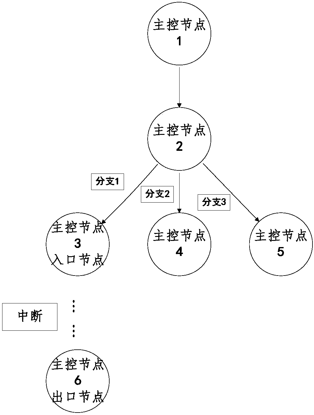
[0076] Such as image 3 , Figure 4 as shown, image 3 shows a structure of the main control flow graph, including the main control node, branch 1, branch 2, branch 3 and the directed edges between each node, Figure 4 shows a structure of interrupt processing control flow graph, including interrupt node, branch 1, branch 2, branch 3 and the directed edges between each node, set Figure 4 The interrupt handling control flow graph shown in image 3 The interrupt handler for the interruption of the master control flow graph, and each node is executed only once, then the worst path analysis process is:

[0077] 1) Merge the marked nodes in the same branch in the main control program into one node;

[0078] 2) Merge all marked nodes in the same branch in the same interrupt handler in the branch corresponding to the main control program of the appeal into one node.

[0079] Among them, ci represents the instruction cycle in the basic block i, and ni represents the number of ...


PUM


Abstract

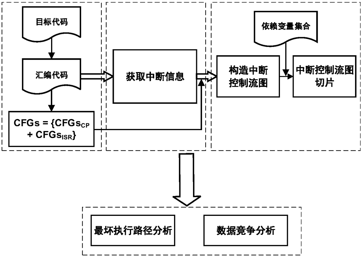
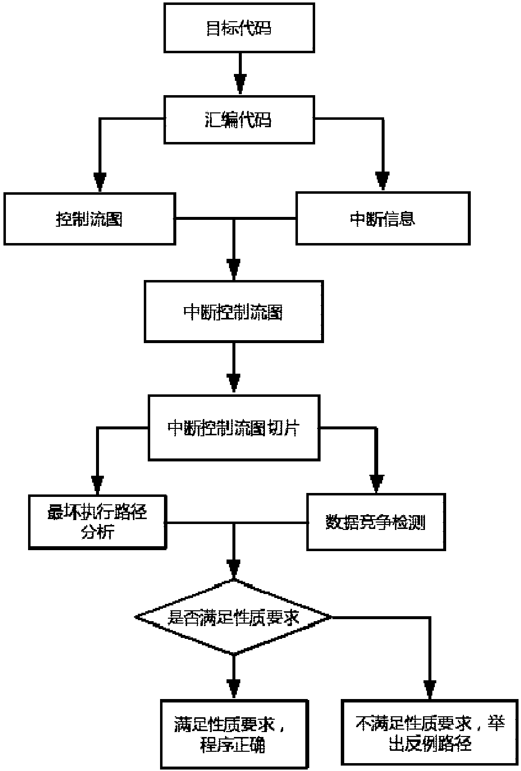
The invention discloses an interruption control flow diagram-based interruption verification method. The method comprises the following steps of: carrying out a disassembling operation on a target code of an interruption driving program so as to obtain an assembly code; constructing an interruption control flow diagram according to the assembly code; slicing the interruption control flow diagram to obtain interruption control flow diagram slices; and verifying time safety and memory safety of the interruption control flow diagram according to the interruption control flow diagram slices. According to the method, control flow information of the interruption driving program is described by adoption of the interruption control flow diagram, and the interruption control flow diagram is slicedby utilizing a program slicing technological thought so as to analyze and verify the time safety and memory safety of the target code. The method has the advantages of putting forward model-interruption control flow diagrams of interruption control flow structures, verifying two most common problems of the interruption driving program in a same model, and improving the reliability and safety of interruption driving program verification.

Description

technical field [0001] The invention relates to the field of static analysis of computer codes, in particular to an interrupt verification method based on an interrupt control flow graph, which is used to verify the time safety and memory safety of an interrupt driver. Background technique [0002] Today, with the rapid development of information technology and mobile Internet, the development of embedded real-time systems has also made remarkable progress, and is widely used in computer-related industries, such as: manufacturing, medical, transportation and communication industries. In addition, embedded real-time systems are widely used in key fields such as energy, aerospace, and military affairs. Therefore, once these systems make mistakes, it will cause immeasurable losses. Particularly important. In fact, the correctness and reliability of the real-time system work not only depends on the results produced by the system operation, but also depends on the time required ...

Claims


Application Information

Patent Timeline
IPC IPC(8): G06F11/36
CPCG06F11/3624G06F11/366
Inventor 史建琦佘庆黄滟鸿郭欣熊家文毛侠
Owner EAST CHINA NORMAL UNIVERSITY
Learn More