Defoaming tank

A defoamer and foam removal technology, applied in the direction of foam dispersion/prevention, degassing by filtering liquid, etc., can solve the problems of pollutant discharge, defoamer pollution, material liquid loss, etc., and achieve compact structure, high efficiency and low operating cost Low cost and easy maintenance

Inactive Publication Date: 2018-08-31
南京圣卡孚科技有限公司
View PDF6 Cites 1 Cited by
  • Summary
  • Abstract
  • Description
  • Claims
  • Application Information

AI Technical Summary

Problems solved by technology

[0006] 4) When the foam overflows, it will cause unnecessary loss of the material liquid;
[0007] 5) It is easy to form mist entrainment or pollutant discharge problems
[0008] In the process of industrial production, foam needs to be removed to avoid the above hazards. The commonly used defoaming methods include three types: storage, physical intervention, and chemical methods. Among them, the natural defoaming process takes a long time and is applicable to very limited occasions; In production occasions with strict composition requirements, chemical defoaming method is difficult to accept, and it will also bring secondary problems such as defoaming agent pollution; while the commonly used physical method of defoaming is usually not easy to completely defoam, and the chemical production conditions are complex, involving high temperature, High pressure, negative pressure, flammable, explosive and other harsh environments, general physical defoaming methods are difficult to meet

Method used


Image

  • Defoaming tank

Examples


Embodiment Construction

[0024] In order to make the technical solutions of the present invention clearer and clearer to those skilled in the art, the present invention will be further described in detail below in conjunction with the examples and accompanying drawings, but the embodiments of the present invention are not limited thereto.

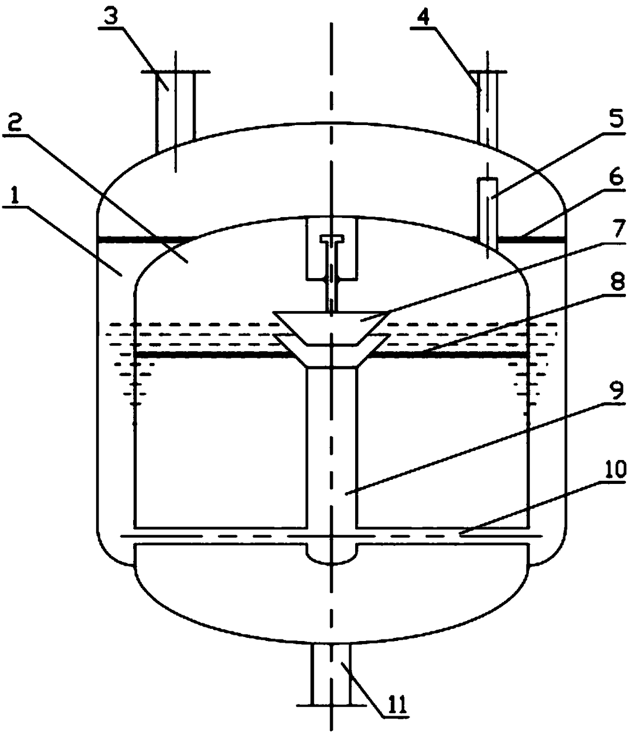
[0025] Such as figure 1 As shown, a kind of defoaming irrigation provided in this embodiment includes an outer tank body 1 with a cavity and an inner tank body 2 at least partially arranged in the outer tank body 1 and having a cavity; the outer tank body The two sides of the top of 1 are respectively provided with feed inlet 3 and outer tank body tail gas outlet 4, and the cavity of described outer tank body 1 is provided with at least one air bubble pre-separation weir 6; The top of described inner tank body 2 is provided with There is an inner tank exhaust port 5, and at least one coalescing and defoaming plate 8, a central pipe 9 and a liquid distribution pipe ...


PUM

PropertyMeasurementUnit
pore sizeaaaaaaaaaa

Abstract

The invention discloses a defoaming tank and belongs to the technical field of chemical equipment. The defoaming tank comprises an outer tank and an inner tank, wherein a cavity is formed inside the outer tank; the inner tank is at least partially arranged inside the outer tank; a cavity is formed inside the inner tank. The defoaming tank is characterized in that a feeding hole and an outer tank tail gas hole are respectively formed in two sides of the top of the outer tank; at least one gas foam pre-separation weir is arranged inside the cavity of the outer tank; an inner tank tail gas hole is formed in the top of the inner tank; at least one coalescence defoaming plate, a central tube and a liquid blending tube are arranged inside the cavity of the inner tank; a liquid outlet is formed in the bottom of the inner tank. The defoaming tank is free of chemical reagent, foams on the surface of a liquid can be rapidly removed by using the device, and the defoaming tank is simple and sealedin structure, free of extra separation power, widely applicable to multiple harsh environments with high temperatures, high pressure, negative pressure, combustibility, explosiveness and the like inchemical production, and in addition is compact and efficient in structure, simple and convenient to maintain, convenient to use, low in operation cost and applicable to chemical technique transformation and optimization upgrading.

Description

technical field [0001] The invention relates to a defoaming tank, in particular to a pure liquid-phase gas-foam separation defoaming tank in a harsh chemical production environment, and belongs to the technical field of chemical equipment. Background technique [0002] Foam is a dispersed system formed by the dispersion of fine insoluble gas bubbles in a liquid. The existence of foam will bring the following significant hazards to industrial production: [0003] 1) The existence of foam will change the material density and affect the mass transfer efficiency and heat transfer capacity of the reaction; [0004] 2) Rapidly reduce the flow rate of the production unit and increase power consumption; [0005] 3) Reduce product appearance and even storage time; [0006] 4) When the foam overflows, it will cause unnecessary loss of the material liquid; [0007] 5) It is easy to cause mist entrainment or pollutant discharge problems. [0008] In the process of industrial product...

Claims


Application Information

Patent Timeline
Patent Type & Authority Applications(China)
IPC IPC(8): B01D19/02
CPCB01D19/0031B01D19/02
Inventor 陆剑鸣陈忠吕攀
Owner 南京圣卡孚科技有限公司
Why Eureka
Try Eureka