Material sleeve path optimization method applied to common edge cutting of pipe parts

A path optimization and cutting path technology, applied in data processing applications, forecasting, laser welding equipment, etc., can solve the problems of not supporting common edge cutting, waste of pipe raw materials, and poor processing effects, so as to improve the cutting process and reduce the loss of raw materials , Reduce the effect of laser and auxiliary gas consumption

Active Publication Date: 2018-08-31
FOSHAN HONGSHI LASER TECH
View PDF4 Cites 6 Cited by
  • Summary
  • Abstract
  • Description
  • Claims
  • Application Information

AI Technical Summary

Problems solved by technology

But for multi-notch, and the notch changes, there is no way to deal with it. In addition, when geometric compensation is required in bevel cutting, general nesting and nesting do not support co-edge cutting. Each part requires a minimum of two cuts to truncate
Without an optimized cutting path, on the one hand, the cutting path is long, the equipment loss is large, the efficiency is low, and the production capacity is seriously affected; on the other hand, after repeated processing at the joints of the parts, the pipe will be overheated and the processing effect will be poor
Finally, the inability to share edges will lead to cutting excess material, which will cause waste of pipe raw materials

Method used


Image

  • Material sleeve path optimization method applied to common edge cutting of pipe parts
  • Material sleeve path optimization method applied to common edge cutting of pipe parts
  • Material sleeve path optimization method applied to common edge cutting of pipe parts

Examples


Embodiment Construction

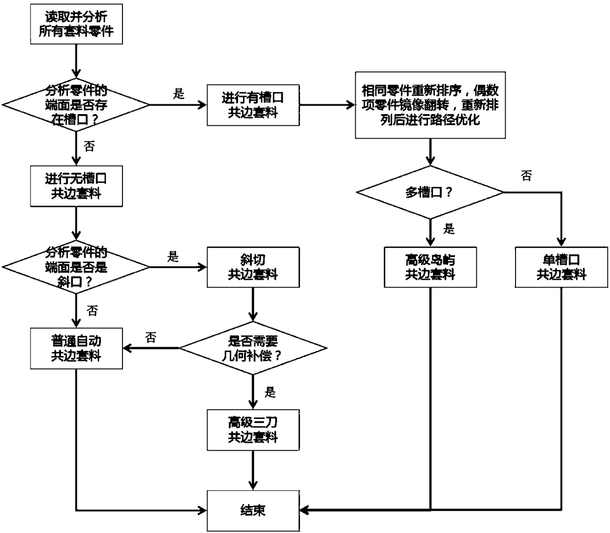
[0033] Such as figure 1 The flow chart of a nesting path optimization method applied to co-edge cutting of pipe parts is shown, and its main steps are as follows:

[0034] 1. A nesting path optimization method applied to co-edge cutting of pipe parts, characterized in that it comprises the following steps:

[0035] (1) Read and display all parts involved in nesting;

[0036] (2) Traverse the head and tail faces of all parts, check whether there is a notch on the contour on the end face, if there is no notch, go to step (3), if there are one or more notches, then directly skip to step (7);

[0037] (3) Execute non-notch co-edge nesting cutting, analyze the end face that needs to be cut, if it is a straight cut end face, then proceed to step (4), if it is a beveled end face, then proceed to step (5);

[0038] (4) Execute common automatic co-edge nesting cutting;

[0039] (5) Execute oblique cutting and co-edge nesting cutting, analyze whether geometric compensation is needed...


PUM


Abstract

The invention provides a material sleeve path optimization method applied to common edge cutting of pipe parts. On the premise that machine tool equipment, the pipe raw material and machined parts arenot changed, the cutting path is optimized, so that the purpose that the raw material of the pipe is saved, the energy consumption of the laser is reduced, the gas consumption is assisted, and the total movement path of the machine tool is reduced is achieved, and meanwhile, the method has positive significance for improving the cross section quality of part products and prolonging the service life of equipment.

Description

technical field [0001] The invention relates to the field of nesting of pipe laser processing parts, in particular to a nesting path optimization method for common-edge cutting of pipe parts. Background technique [0002] Laser pipe cutting machine is a special equipment for cutting, welding, marking, engraving, surface treatment, fine processing and other processes of pipes by using high-energy laser beams. In the laser cutting processing industry, most of them need to use automatic nesting software. After nesting the parts on the set pipe, the processing code is output for processing. In most cases, nesting software can basically get better nesting results, that is, to nest as many parts as possible on limited materials, but the processing path is not necessarily optimal, especially the part-to-part The cutting path is not optimal, resulting in long cutting path and high equipment loss. Therefore, how to optimize the cutting path between parts during nesting, to achieve h...

Claims


Application Information

Patent Timeline
IPC IPC(8): B23K26/38B23K26/70G06Q10/04
CPCB23K26/38B23K26/70G06Q10/047
Inventor 夏宇锐刘洋罗少春常勇
Owner FOSHAN HONGSHI LASER TECH
Why Eureka
Try Eureka