Decoupling control method of airborne LiDAR attitude angle compensation device

A compensation device and decoupling control technology, applied in the field of decoupling control, can solve problems such as control systems that are not suitable for rapid response, complex algorithms, and large amount of calculations

Active Publication Date: 2018-08-31
SHANDONG UNIV OF TECH
View PDF7 Cites 7 Cited by
  • Summary
  • Abstract
  • Description
  • Claims
  • Application Information

AI Technical Summary

Problems solved by technology

Traditional decoupling uses pre-compensation, which is more suitable for linear steady systems; adaptive decoupling is to identify the controlled object to realize the decoupling control of unknown parameters or time-varying systems, mainly to solve the dyn

Method used


Image

  • Decoupling control method of airborne LiDAR attitude angle compensation device
  • Decoupling control method of airborne LiDAR attitude angle compensation device
  • Decoupling control method of airborne LiDAR attitude angle compensation device

Examples


Embodiment Construction

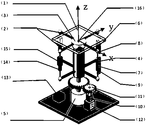
[0018] figure 1It is the mechanical structure of the airborne lidar attitude angle compensation device. The reflector (1) is supported by four mirror support rods (2) made of titanium alloy to form a cross. The magnetic small hemisphere universal bearing (3) and the column ( 4) Connection, there is a spherical concave surface on the column, so that the magnetic small hemisphere and the spherical concave surface are magnetically attracted, and the magnetic small hemisphere can flexibly rotate around the x-axis and y-axis. The z-axis adopts a vertical shaft mode, and the lower end of the column (4) is installed in the vertical rolling bearing (5). The x-axis direct motion motor (6) and the y-axis direct motion motor (7) are used to respectively drive the mirror (1) to swing up and down around the x-axis and y-axis, and the x-axis grating displacement sensor (8) and the y-axis grating displacement The sensors (9) respectively measure the actual displacements of the x-axis direc...


PUM


Abstract

The invention relates to a decoupling control method of an airborne LiDAR attitude angle compensation device. In order to compensate effects on airborne laser radar measurement point cloud imposed byhelicopter-borne platform attitude angle change, an attitude angle compensation device is designed. The device is a tri-axle turntable, and there is control coupling, so a decoupling control method isprovided. The method comprises steps of firstly, establishing a mathematical model of an attitude angle compensation device dynamic system and proving the reversibility of the attitude angle compensation device dynamic system; then, establishing a neural network inverse system model of the attitude angle compensation device dynamic system, acquiring neural network learning data and carrying out offline training on the neural network; then, comparing output of the neural network inverse system with an expected input value, and sending the differential value into a feedforward controller to beused for correcting a control voltage signal of the attitude angle compensation device dynamic system; and finally, by combining a fuzzy-PID controller of a closed-loop feedback loop, forming a feedforward-feedback composite controller. Thus, real-time decoupling of the attitude angle compensation device dynamic system is achieved, control precision and anti-interference are improved and dynamic control performance is improved.

Description

technical field [0001] The invention relates to a decoupling control method for realizing an airborne LiDAR attitude angle compensation device control system by using a neural network inverse system. Background technique [0002] As a new and effective 3D imaging technology, airborne LiDAR has been widely used in many fields such as terrain mapping and urban modeling. During the working process of airborne LiDAR, the attitude angle of the airborne platform will change in real time, which will affect the quality of the measured laser point cloud and reduce the accuracy of subsequent 3D imaging. Therefore, it is necessary to design an airborne LiDAR attitude angle compensation device that can compensate in real time the adverse effects of changes in the three-axis attitude angle of the airborne platform on the airborne LiDAR measurement. However, the airborne LiDAR attitude angle compensation device is a complex multi-input multi-output, strong coupling system. In order to im...

Claims


Application Information

Patent Timeline
IPC IPC(8): G05B13/02G05B13/04G05B11/42
CPCG05B11/42G05B13/027G05B13/042
Inventor 王建军李云龙范媛媛苗松
Owner SHANDONG UNIV OF TECH
Why Eureka
Try Eureka