Powered artificial ankle based on electro-hydraulic direct drive technology

A direct-drive, electro-hydraulic technology, applied in artificial legs, medical science, prostheses, etc., can solve problems such as inconvenience, consumption, adjustment of gait and control of torque

Inactive Publication Date: 2018-09-04
黄其涛
View PDF7 Cites 8 Cited by
  • Summary
  • Abstract
  • Description
  • Claims
  • Application Information

AI Technical Summary

Problems solved by technology

Most of the existing ankle prostheses are passive and cannot provide power for the human body, so that patients need to consume more than 30% more energy for walking than healthy people. At the same time, when people walk at variable speeds, passive ankle prostheses cannot actively Adjust gait and control torque in real time, which brings great inconvenience to people walking

Method used


Image

  • Powered artificial ankle based on electro-hydraulic direct drive technology
  • Powered artificial ankle based on electro-hydraulic direct drive technology
  • Powered artificial ankle based on electro-hydraulic direct drive technology

Examples


Embodiment 1

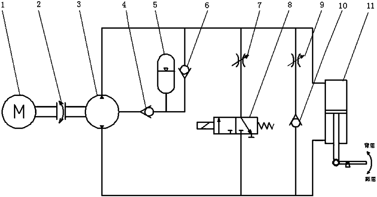
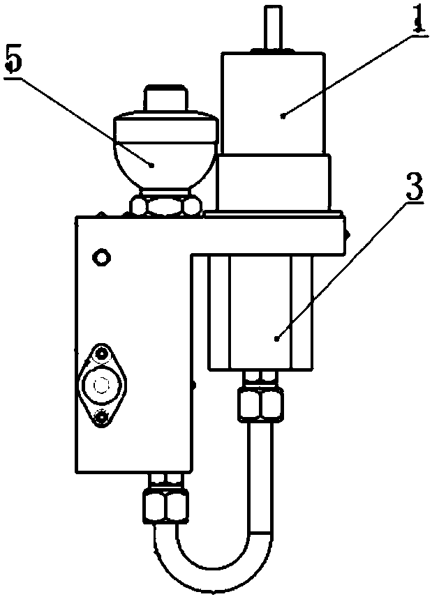
[0023] A powered artificial ankle based on electro-hydraulic direct drive technology, including an electro-hydraulic direct drive actuator, a lower leg prosthesis, an angle sensor, a force sensor, and a control module. signal connections such as Figure 1-2 As shown, the electro-hydraulic direct drive actuator includes a servo motor 1, a hydraulic cylinder 11, a bidirectional gear pump 3, a hydraulic valve block and an accumulator 5, the hydraulic valve block is connected to the hydraulic cylinder 11, the servo motor 1 and the bidirectional gear The pump 3 is fixed on the hydraulic valve block, the servo motor 1 and the two-way gear pump 3 are connected through the coupling 2; the hydraulic valve block is equipped with three one-way valves 4.6.10, two throttle valves 7.9 and two-position three-way solenoid The reversing valve 8; the oil inlet of the first one-way valve 10 is connected with the oil outlet of the first throttle valve 9; the oil outlet of the two-position three-w...

Embodiment 2

[0025] The movement process of a powered artificial ankle based on electro-hydraulic direct drive technology is as follows: Figure 5 Shown:

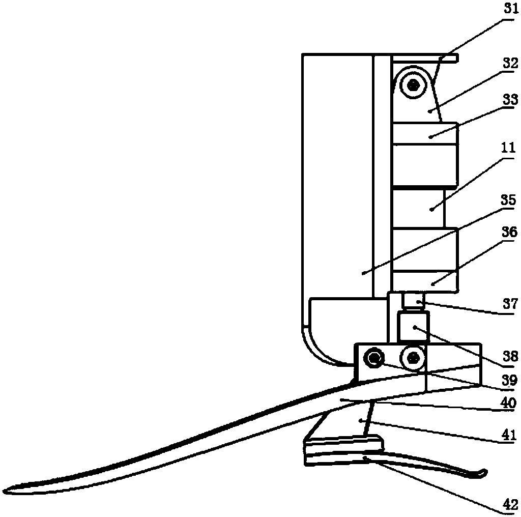
[0026] Plantarflexion control: the rear heel touches the ground first, the servo motor does not work at this time, and the artificial ankle is in a passive state. The first throttle valve 9, the first one-way valve 10, and the hydraulic cylinder 11 form a closed loop. The first throttle valve 9. The damping is large, which buffers the movement of the piston rod of the hydraulic cylinder 11 at this time, and achieves the shock-absorbing and buffering effect of controlling the plantar flexion stage when the heel 42 touches the ground. From the heel 42 touches the ground to the entire arch 40, the plantar flexion angle gradually Increase, and reach the maximum value when the entire arch 40 touches the ground. At this stage, the artificial ankle acts as a buffer, which is equivalent to a linear spring, and the torque of the artificial ankle...


PUM


Abstract

The invention aims to provide a powered artificial ankle based on an electro-hydraulic direct drive technology, and aims to help a below-knee amputee to restore normal walking ability. The powered artificial ankle comprises an electro-hydraulic direct drive executing mechanism, a below-knee prothesis, an angle sensor, a force sensor and a control module, the control module is in electric signal connection with the angle sensor, the force sensor and the electro-hydraulic direct drive executing mechanism, a motor drives a gear pump, the gear pump drives a hydraulic cylinder to provide power at apower plantar flexion stage and posture adjustment at a swinging stage when a human body walks, a hydraulic system provides buffer for the plantar flexion stage and a dorsiflexion phase, postures ofthe artificial ankle are judged by measuring data of the force sensor and the angle sensor in real time, and motion of next step of the artificial ankle is guided. Besides, according to the powered artificial ankle, and the step speed of the artificial ankle can further be adjusted, so that various different motion speeds and motion requirements are met.

Description

technical field [0001] The invention relates to machinery, hydraulic pressure and control technology, specifically a power artificial ankle based on electro-hydraulic direct drive technology. Background technique [0002] The powered artificial ankle based on electro-hydraulic direct drive technology is an important ankle prosthesis. At present, there are 650 million disabled people in the world, accounting for about 10% of the world's total population, 80% of which are distributed in developing countries. In my country, there are about 24.72 million physically disabled patients, including 2.26 million amputee people. There is a huge social group Requires prosthetics, especially ankle prostheses. Most of the existing ankle prostheses are passive and cannot provide power for the human body, so that patients need to consume more than 30% more energy for walking than healthy people. At the same time, when people walk at variable speeds, passive ankle prostheses cannot actively ...

Claims


Application Information

Patent Timeline
Patent Type & Authority Applications(China)
IPC IPC(8): A61F2/66A61F2/68A61F2/74
CPCA61F2/66A61F2/6607A61F2/68A61F2002/5006A61F2002/6614A61F2002/6827A61F2/74A61F2/741
Inventor 黄其涛罗剑
Owner 黄其涛
Why Eureka
Try Eureka