Automatic alignment center rack

An automatic centering and centering technology, which is applied in the direction of grinding workpiece brackets, large fixed members, metal processing machinery parts, etc., can solve the problems of high machining accuracy of hydraulic components, inability to use center frame stiffness, impact, etc., to achieve installation It is convenient and quick to disassemble the workpiece, shorten the auxiliary processing time, and the structure of the transmission system is simple.

Inactive Publication Date: 2018-09-04
CHANGZHOU COLLEGE OF INFORMATION TECH
View PDF3 Cites 6 Cited by
  • Summary
  • Abstract
  • Description
  • Claims
  • Application Information

AI Technical Summary

Problems solved by technology

Using the conventional closed steady rest, it takes a long time to adjust the concentricity of the workpiece, the precision is low, and the efficiency is low
[0003] At present, most of the existing self-centering steady frames use hydraulic cylinders as the driving force, which requires a special hydraulic station. The hydraulic components require high processing accuracy, difficult processing and assembly, limited use of space, and the production environment is prone to oil pollution and other shortcomings.
There are also some self-centering steady rests that use motor direct drive, but only one moving speed can be used during the centering process. If you choose a faster centering speed, it will cause an impact when the centering roller contacts the surface of the workpiece, directly It affects the accuracy and surface quality of the workpiece; if you choose a slower centering speed, the processing efficiency will be significantly reduced, and this method keeps the motor in the working state throughout the processing process, with high energy consumption and high heat generation. Reduced lifespan
At present, whether it is a hydraulic or electric automatic centering center frame or a manual adjustment center frame, it can only be used to support a cylindrical shaft diameter, and cannot solve the support problem of a conical shaft diameter.
For some slender shaft parts, there is no cylindrical shaft section for support at one end (only a long conical surface), and the steady frame cannot be used to improve its rigidity during processing, resulting in very high processing efficiency and processing accuracy for such parts. Low
At present, for the slender shaft parts with conical surface, only one end is clamped, the other end is clamped by the top or both ends are clamped. If the long diameter is relatively large, the rigidity of the workpiece is poor, and the workpiece is subjected to cutting force. It will produce large bending deformation, and only a small cutting amount can be used during processing. Not only the processing efficiency is extremely low, but also it is difficult to obtain high processing accuracy.

Method used


Image

  • Automatic alignment center rack
  • Automatic alignment center rack
  • Automatic alignment center rack

Examples


Embodiment 1)

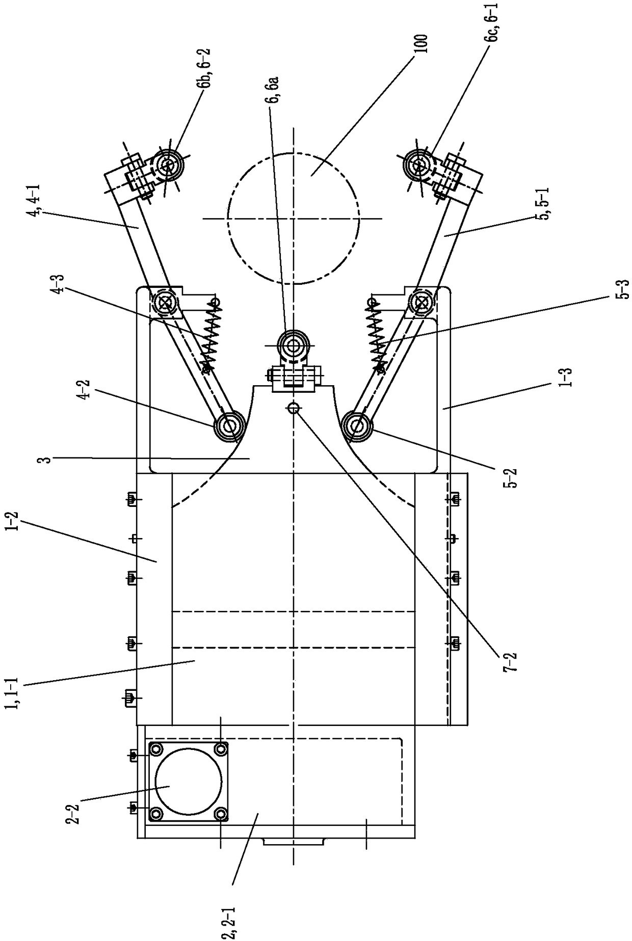
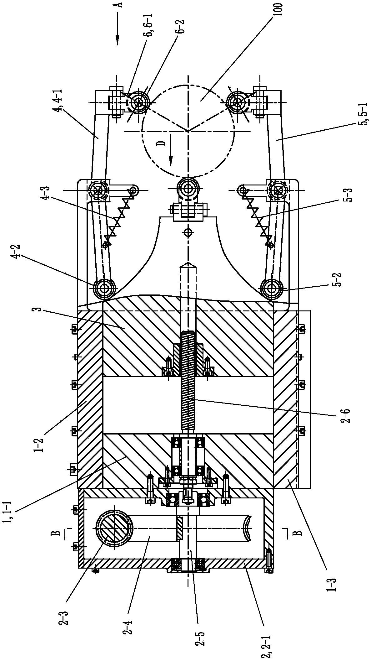
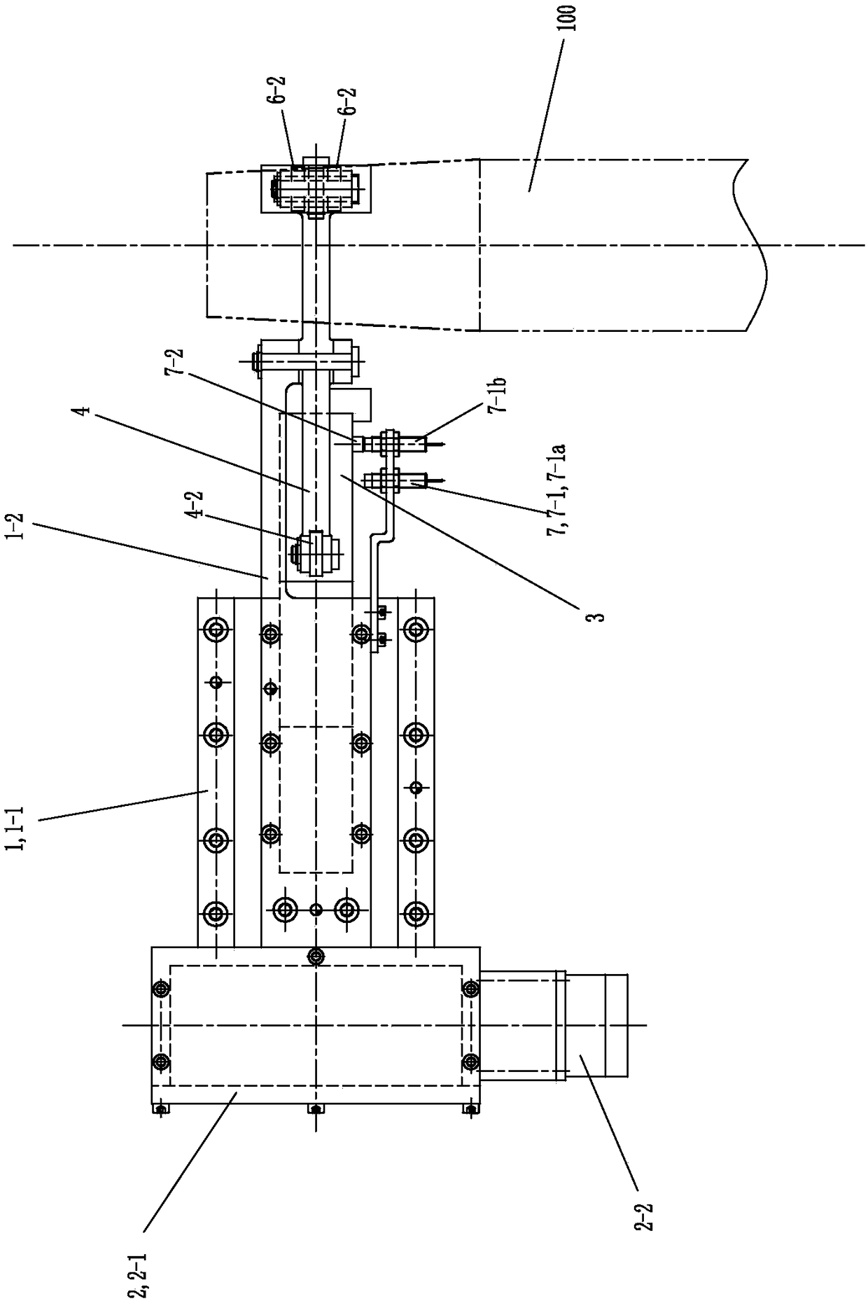
[0039] See Figure 1 to Figure 10 , The automatic centering center frame of the present invention includes a chassis 1, a driving device 2, a translation cam 3, an upper pressing rod assembly 4, a lower pressing rod assembly 5, a pressure head assembly 6 and a travel switch assembly 7.

[0040] See Figure 1 to Figure 4 and Figure 8 to Figure 10 , The chassis 1 includes a body 1-1, an upper bracket 1-2 and a lower bracket 1-3. The upper bracket 1-2 is fixed on the upper side of the body 1-1, and the right end extends out of the body 1-1. The lower bracket is fixedly arranged on the lower side of the body 1-1, and the right end extends out of the body 1-1. Thus, the body 1-1, the upper bracket 1-2 and the lower bracket 1-3 form a box structure with an opening to the right. The translation cam 3 is slidingly arranged between the body 1-1, the upper bracket 1-2 and the lower bracket 1-3, and the translation cam 3 is driven by the driving device 2 to move left and right.

[00...


PUM


Abstract

The invention discloses an automatic alignment center rack. The automatic alignment center rack is characterized by comprising a machine box, a driving device, a translation cam, an upper pressing rodcomponent, a lower pressing rod component and pressing head components, the translation cam is arranged inside the machine box in a left and right sliding manner and is driven by the driving device to move left and right, an upper pressing rod on the upper pressing rod component and a lower pressing rod are made to swing by the translation cam to make the pressing head components located on the upper pressing rod and the lower pressing rod and the pressing head component on the translation cam be simultaneously closed to the axis of a workpiece to be machined, so that the workpiece to be machined is supported, wheel support racks of the pressing head components automatically rotate according to the shape of the outer edge surface of the workpiece to be machined, and two support wheels ofeach wheel support rack are guaranteed to be pressed tightly against the workpiece to be machined simultaneously.

Description

technical field [0001] The invention relates to the technical field of mechanical processing equipment, in particular to an automatic centering center frame for auxiliary support for processing long-axis mechanical parts. Background technique [0002] The center frame is an auxiliary support device used in the turning or grinding process of slender shaft parts, which makes it possible for high-precision machining of ultra-thin optical shafts, precision screw rods, ball screws and other parts. The conventional closed center frame used on horizontal lathes or cylindrical grinders is a combined structure of upper and lower two bodies, and three centripetal mandrels support the workpiece. When clamping the workpiece, it is necessary to open the upper body of the center frame, close the upper body after loading the workpiece, rotate the workpiece according to the circular runout value, adjust the axial movement of the mandrel, and achieve the coincidence between the support of th...

Claims


Application Information

Patent Timeline
Patent Type & Authority Applications(China)
IPC IPC(8): B23Q1/76B24B41/06
CPCB23Q1/763B24B41/065
Inventor 苏沛群宫亚梅涂琴
Owner CHANGZHOU COLLEGE OF INFORMATION TECH
Why Eureka
Try Eureka