
Sea wind wave dynamic load test device and method

A technology of dynamic loading and test equipment, applied in the direction of program control, instrument, electrical program control, etc., can solve the problems that the frequency and amplitude of cyclic load cannot be adjusted, and the operation of test equipment is not easy, etc., and achieve simple structure, easy operation and high degree of automation Effect

Active Publication Date: 2018-09-04
QINGDAO TECHNOLOGICAL UNIVERSITY
View PDF10 Cites 1 Cited by
  • Summary
  • Abstract
  • Description
  • Claims
  • Application Information

AI Technical Summary

Problems solved by technology

Existing laboratory test equipment cannot meet the requirements of simulating the external force exerted by real sea wind and waves on piles, and the test equipment is not easy to operate, and the frequency and amplitude of cyclic load cannot be adjusted according to time. Therefore, it is necessary to design a dynamic loading test device for sea wind and waves to meet the requirements of pipe pile tests under simulated offshore wind and waves

Method used


Image

  • Sea wind wave dynamic load test device and method
  • Sea wind wave dynamic load test device and method

Examples


Embodiment 1

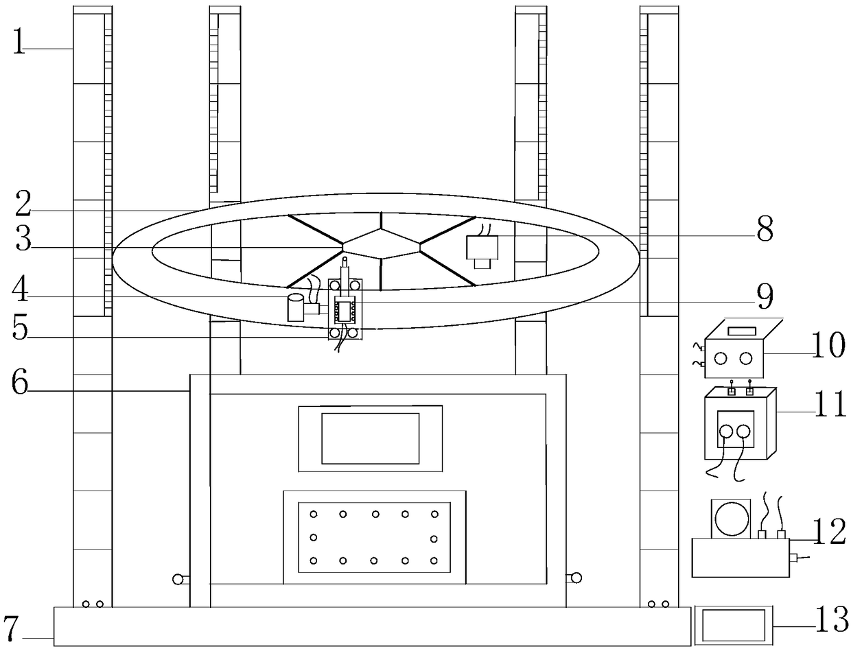
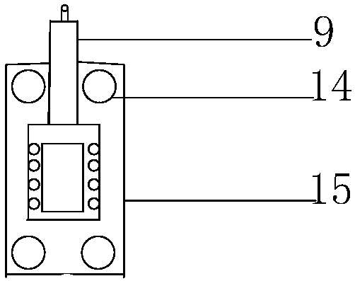
[0015] The main structure of the sea wind and wave dynamic loading test device described in this embodiment includes a reaction force column 1, a horizontal circular track 2, a six-degree-of-freedom information collector 3, a frequency conversion motor 4, a sliding block 5, a model box 6, a base 7, information Processor 8, servo motor 9, information transmitter 10, PLC operation controller 11, oil pump 12 and servo loading controller 13, wherein the horizontal circular track 2, sliding block 5, and frequency conversion motor 4 form a horizontal circular displacement control system, Servo motor 9, oil pump 12 and servo loading controller 13 form a servo loading system, six degrees of freedom information collector 3, information processor 8, information transmitter 10, and data lines form a displacement feedback information system, and PLC operation controller 11 controls In the system, the model box 6 is installed in the middle of the base 7, four reaction force columns 1 are ve...

Embodiment 2

[0022] In this embodiment, the specific process of using the offshore wind and wave dynamic loading test device to simulate the pipe pile test under the sea wind and wave is as follows:

[0023] (1) First, the variable frequency motor 4 is connected to the control system through the data line, and the control system is opened to check whether the variable frequency motor 4 can run normally on the horizontal circular track 2;

[0024] (2) Then the six degrees of freedom information collector 3, the information processor 8, and the information transmitter 10 in the displacement feedback information system are connected by data lines, start the displacement feedback information system, and check whether each part works normally;

[0025] (3) The oil pump 12 is connected with the servo motor 9 through the oil pipe, then the servo loading controller 13 is connected with the oil pump 12 through the data line, and the servo loading controller 13 is opened to check whether the servo lo...


PUM


Abstract

The invention belongs to the technical field of marine testing, and relates to a sea wind wave dynamic load test device and method. A model box is arranged in the middle of a base. Four reaction forcecolumns are vertically arranged at four corners of the base. A horizontal circular track is arranged among four reaction force columns. Pulleys of a sliding block are fixed on the horizontal circulartrack. One end of a frequency conversion motor is connected with a servo load system, and the other end is fixed on the sliding block. A servo motor is fixed on the sliding block. An oil pump is connected with the servo motor. A servo load controller is arranged on one side of the base and is connected with the oil pump. An information transmitter is connected with a control system and an information processor through data lines. The information processor is connected with a six-degree-of-freedom information collector through a data line. The six-degree-of-freedom information collector is arranged in the middle of the horizontal circular track. The sea wind wave dynamic load test device has the advantages of simple structure, easy operation, high degree of automation, safety, reliabilityand quick test, and is free of manual assistance.

Description

Technical field: [0001] The invention belongs to the technical field of marine experiments, and relates to a device and method for a dynamic loading test of sea wind and waves. Background technique: [0002] With the rapid development of modern science and technology, my country's increasingly stringent environmental protection standards and changes in energy structure, marine engineering will show explosive growth. Offshore and coastal projects such as cross-sea bridges, offshore oil field exploitation, and offshore wind power generation are developing rapidly. Pile foundation is one of the most important foundation forms used in offshore engineering and coastal engineering. On the premise of ensuring the safety and reliability of pile foundation, the requirements for shortening construction period, saving project cost, prolonging service life and reducing maintenance work are constantly increasing. At present, most of the offshore pile foundations are large-diameter open p...

Claims


Application Information

Patent Timeline
Patent Type & Authority Applications(China)
IPC IPC(8): G05B19/05
CPCG05B19/054G05B2219/13099
Inventor 刘俊伟王明明赵国晓赵彦平
Owner QINGDAO TECHNOLOGICAL UNIVERSITY
Learn More