Resonant pressure sensor and manufacturing method thereof

A pressure sensor and resonant technology, applied in the fields of micro-inertial sensors, resonant pressure sensors and their preparation, can solve the problems of accuracy being affected by co-vibration mass, increasing the difficulty of closed-loop control, unstable excitation and detection, etc. Stable excitation and detection, minimization of energy transfer, effect of energy transfer reduction

Active Publication Date: 2018-09-07
HEFEI UNIV OF TECH
View PDF10 Cites 34 Cited by
  • Summary
  • Abstract
  • Description
  • Claims
  • Application Information

AI Technical Summary

Problems solved by technology

[0004] For the existing silicon micro-resonant pressure sensor, when the pressure-sensitive diaphragm is deformed under pressure, the height of the resonator will change, but the position of the excitation and detection comb teeth will not change, so the excitation force and detection signal will both decrease, so that not...

Method used


Image

  • Resonant pressure sensor and manufacturing method thereof
  • Resonant pressure sensor and manufacturing method thereof
  • Resonant pressure sensor and manufacturing method thereof

Examples


Embodiment 1

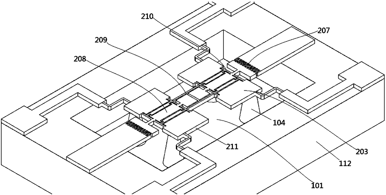
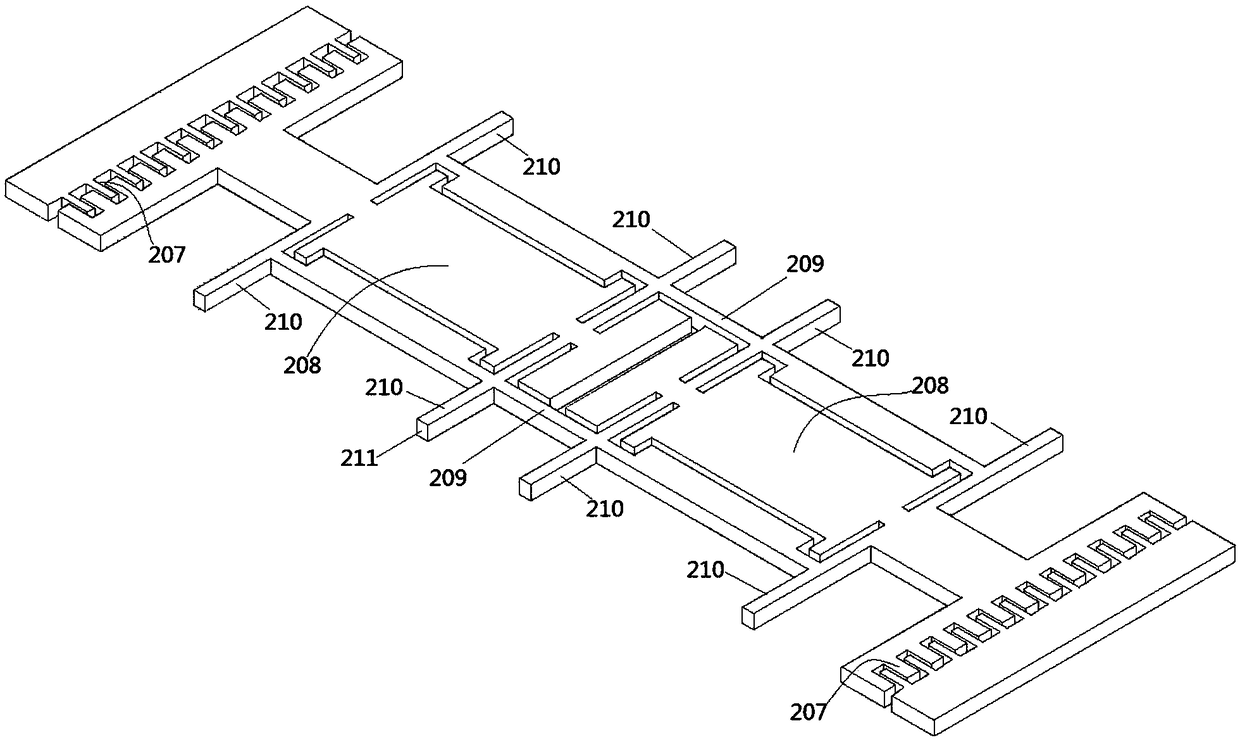
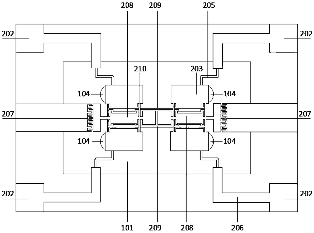
[0032] Such as figure 1 and image 3 As shown, a resonant pressure sensor includes: a rectangular bottom SOI wafer 112, the bottom SOI wafer 112 is in the shape of a zigzag, with a cavity in the middle. A layer of pressure detection sensitive film 101 is provided at the bottom of the cavity; four mutually symmetrical silicon islands 104 are provided in the cavity, and the silicon islands 104 are fixedly connected to the top surface of the pressure detection sensitive film 101 . In the present invention, the stress is transmitted through four silicon islands 104 , specifically, the four silicon islands 104 are symmetrically distributed on the diagonal of the pressure sensitive film 101 . The tops of the four silicon islands 104 are suspended with resonators 211; the four corners of the bottom SOI wafer 112 are provided with contact pads 202, and each contact pad 202 passes through the L-shaped track 206 and the S-shaped curved track 205 and the resonator 211 in turn. connect....

Embodiment 2

[0040] A method for preparing a resonant pressure sensor, comprising the steps of:

[0041] (1) Preparation: prepare two double-sided polished SOI silicon wafers, namely the first SOI silicon wafer 214 with a thickness of 475 um and the second SOI silicon wafer 214 with a thickness of 380 um.

[0042] (2) Etching: On the first SOI silicon wafer, etch the 1um thick wafer alignment key 122, the 325um high silicon island 104 and the 150um thick pressure detection sensitive thin film area to make the bottom SOI wafer 112. The etching in this step can adopt traditional KOH etching (wet etching). Such as Figure 6a shown.

[0043] (3) Silicon-silicon bonding: bonding the etched bottom SOI wafer 112 to the top layer of the second SOI silicon wafer 214 using a bonding technique. The bottom SOI wafer 112 and the second SOI silicon wafer are firstly cleaned by a standard cleaning method for silicon-silicon bonding, followed by bonding in a pure oxygen environment, and annealing at 10...


PUM

PropertyMeasurementUnit
Thicknessaaaaaaaaaa
Thicknessaaaaaaaaaa
Thicknessaaaaaaaaaa

Abstract

The invention provides a resonant pressure sensor and a manufacturing method thereof. A resonator uses a resonator structure based on an SOI silicon-based silicon comb double-ended fixed tuning fork structure. A Wheatstone bridge is formed inside the resonator by two piezoresistive materials (silicon after process doping) and two equivalent resistors (undoped silicon). The resistance change of thepiezoresistive materials is changed by a pressure change to detect the change in resonant frequency. Based on the silicon island structure, the pressure sensor structure is designed to transform thedeformation on a pressure-sensitive film into the plane vibration in the direction of the resonator through the silicon island structure, which not only reduces the mechanical coupling of the sensor,but also improves a quality factor and achieves a wide measurement range and high reliability.

Description

technical field [0001] The invention belongs to the field of micro-electromechanical technology, and relates to a micro-inertial sensor, in particular to a resonant pressure sensor based on electrostatic excitation / resistance detection and a preparation method thereof Background technique [0002] Today's silicon micro pressure sensors based on MEMS technology are widely used in military fields such as fighter jets, including flight data systems, environment and cabin pressure, hydraulic systems in the fuselage, engines and auxiliary power equipment, and various other applications, such as Doors, oxygen masks, flight testing and structural monitoring. The number of pressure sensors used in aircraft, jets, propeller planes and helicopters is also enormous. Therefore, the requirements for the performance index of the sensor (including high precision, sensitivity, etc.) and reliability in complex environments are becoming more and more stringent. Aiming at the modern military...

Claims


Application Information

Patent Timeline
IPC IPC(8): G01L1/18
CPCG01L1/183
Inventor 许高斌胡海霖陈兴马渊明王超超
Owner HEFEI UNIV OF TECH
Why Eureka
Try Eureka