Skin reinforced structure antenna reflector and preparation method thereof

An antenna reflector and skin technology, applied in antennas, electrical components, etc., can solve problems such as failure to experimentally verify the correctness of engineering applications, neglect of the functional role of ribs, poor thermal stability of the structure, etc., to achieve the fault tolerance of the laminate High, reduce the factors affecting the accuracy, reduce the weight effect

Inactive Publication Date: 2018-09-07
SHANGHAI COMPOSITES SCI & TECH CO LTD
View PDF14 Cites 5 Cited by
  • Summary
  • Abstract
  • Description
  • Claims
  • Application Information

AI Technical Summary

Problems solved by technology

Therefore, the main body of the reflective surface of the antenna reflector produced in this patent is still a honeycomb sandwich structure, and there are many molding processes, poor thermal stability of the structure, and heavy weight.
[0005] The invention patent application with the application number 201510920136.9 discloses a molding method of a composite material reflector. The molding method disclosed in this patent is that the reflector body and the rib are integrally formed, and the technology used is co-curing molding, but This method is prone to thermal deformation and stress release deformation during co-curing molding
[0006] In the scientific paper "Simulation and Optimization of Composite Thin-walle

Method used


Image

  • Skin reinforced structure antenna reflector and preparation method thereof
  • Skin reinforced structure antenna reflector and preparation method thereof
  • Skin reinforced structure antenna reflector and preparation method thereof

Examples


Embodiment Construction

[0056] The present invention will be described in detail below in conjunction with specific embodiments. The following examples will help those skilled in the art to further understand the present invention, but do not limit the present invention in any form. It should be noted that for those of ordinary skill in the art, several changes and improvements can be made without departing from the concept of the present invention. These all belong to the protection scope of the present invention.

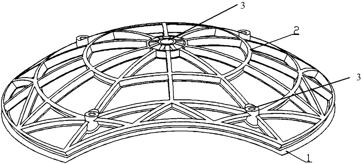
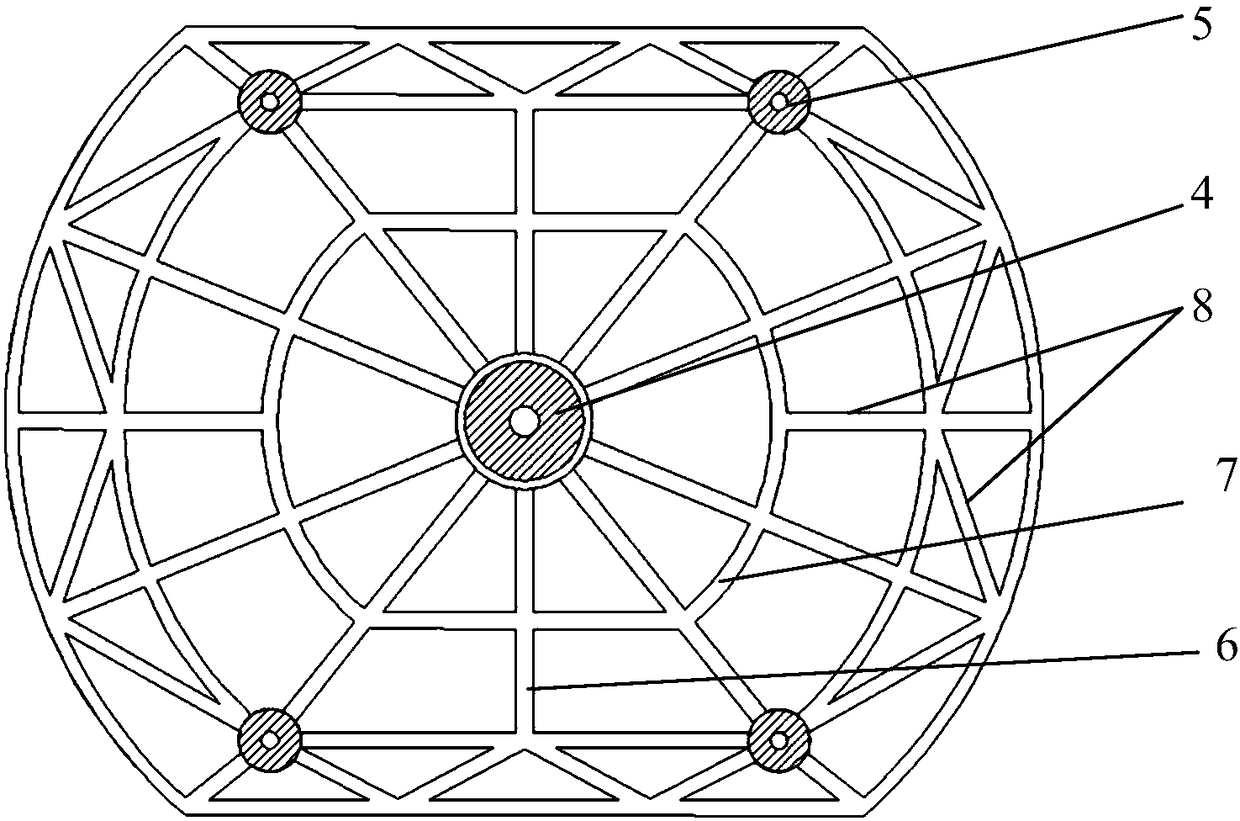
[0057] The invention provides an antenna reflector with a skin reinforced structure, such as Figure 1 to Figure 2 As shown, it includes a reflective surface 1 and a back rib 2, the back rib 2 is arranged on one side of the reflective surface 1; the reflective surface 1 is composed of a single layer of skin, and the back rib 2 is a curved multi-grid frame structure. The reflecting surface 1 is arranged inside the back rib 2.

[0058] Such as figure 2 As shown, the back rib 2 is provided w...


PUM

PropertyMeasurementUnit
Thicknessaaaaaaaaaa

Abstract

The invention provides a skin reinforced structure antenna reflector and a preparation method thereof; the reflector comprises a plane of reflection and back ribs arranged on the side of the plane ofreflection; the plane of reflection comprises a single layer skin; the back ribs are in a curved surface multi-grid frame structure; the reflector preparation method comprises the following steps: S1,respectively making the skin and the back ribs; S2, gluing, assembling and curing the skin with the back ribs; S3, demoulding after curing is done, and obtaining the final product. The rigidity and thermal expansion coefficient of the skin and the back ribs are matched; the back ribs can be integrally designed and moulded with an external interface and a joint; the prepared antenna reflector is light in weight, good in rigidity, high in profile precision, and good in thermal stability; the antenna reflector with the caliber of 2.5m can realize the effect that the profile precision root mean square (RMS) reaches 15um; when the ambient temperature rises from 20 to 120 DEGC or drops to 180 DEG C, the plane of reflection profile thermal deformation RMS value can be only 5um or 12 um.

Description

Technical field [0001] The present invention relates to the technical field of antenna reflectors, in particular to a skin-reinforced structure antenna reflector and a preparation method thereof, and in particular to a light-weight and high-thermal-stability skin-reinforced structure antenna reflector and a preparation method thereof . Background technique [0002] As human beings continue to explore the universe, high-sensitivity and high-resolution spacecraft have become indispensable tools, and high-precision spaceborne antennas have emerged and are in urgent need. At present, antennas are gradually developing in the direction of large aperture, high frequency band, high gain, and high energy density. When the antenna diameter increases and the operating frequency increases, the requirements for the accuracy of the reflecting surface become higher and higher, and the mutual influence and mutual restriction between the electromagnetic and mechanical structural factors of the a...

Claims


Application Information

Patent Timeline
IPC IPC(8): H01Q15/16H01Q15/14
CPCH01Q15/142H01Q15/16
Inventor 周涛叶周军吴文平梁旭豪梁燕民吴鑫锐史耀辉刘艳翟东坤史文锋董晓阳郝旭峰
Owner SHANGHAI COMPOSITES SCI & TECH CO LTD
Why Eureka
Try Eureka