
Novel laser engraving unit equipment control system

A laser engraving and equipment control technology, applied in laser welding equipment, welding equipment, metal processing equipment, etc., can solve problems such as low engraving efficiency, matching results affecting the final optical flow estimation effect, and poor image effect to be engraved.

Inactive Publication Date: 2018-09-11
GUANGDONG TECHN COLLEGE OF WATER RESOURCES & ELECTRIC ENG
View PDF7 Cites 3 Cited by
  • Summary
  • Abstract
  • Description
  • Claims
  • Application Information

AI Technical Summary

Problems solved by technology

[0015] The image to be engraved obtained by existing laser engraving has poor effect; at the same time, the engraving efficiency is low
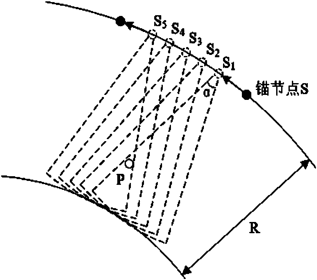
[0016] In the process of moving nodes in engraved images, GPS cannot use high-precision time parameters to replace traditional GPS position information, and there are errors in the efficient positioning of unknown nodes in WSN
[0017] Calculating dense matching requires a considerable cost, and the accuracy of the matching result also directly affects the effect of the final optical flow estimation

Method used


Image

  • Novel laser engraving unit equipment control system
  • Novel laser engraving unit equipment control system
  • Novel laser engraving unit equipment control system

Examples


Embodiment Construction

[0089] In order to further understand the content, features and effects of the present invention, the following examples are given, and detailed descriptions are given below with reference to the accompanying drawings.

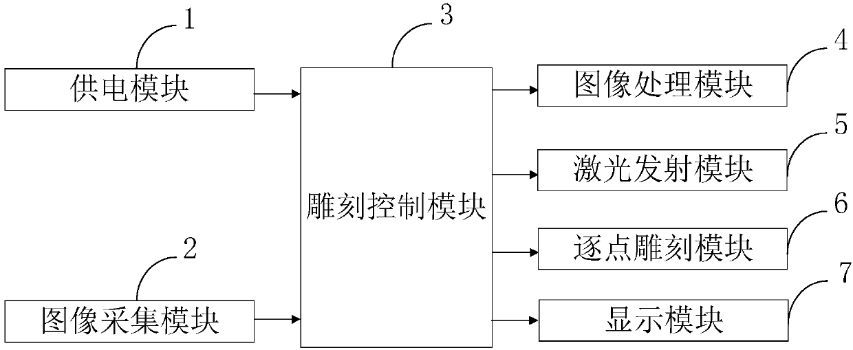
[0090] Such as figure 1 As shown, the novel laser engraving unit device control system provided by the embodiment of the present invention includes: a power supply module 1, an image acquisition module 2, an engraving control module 3, an image processing module 4, a laser emission module 5, a point-by-point engraving module 6, and a display module 7.

[0091] The power supply module 1 is connected with the engraving control module 3, and is used to supply power to the engraving equipment;

[0092] The image acquisition module 2 is connected with the engraving control module 3, and is used to obtain the image to be engraved by the image capture device;

[0093] The engraving control module 3 is connected with the power supply module 1, the image acquisition...


PUM


Abstract

The invention belongs to the technical field of laser engraving, and discloses a novel laser engraving unit equipment control system. The novel laser engraving unit equipment control system comprisesa power supply module, an image acquiring module, an engraving control module, an image processing module, a laser transmission module, a point-by-point engraving module and a display module. According to the novel laser engraving unit equipment control system, the image processing module carries out chrominance compensation on an image to be engraved according to ambient light conditions, for example, color saturation is compensated, or the color gamut range of the image to be engraved is expanded, in consequence, color vividness of the image displayed in ambient light can be improved, and the display effect of display equipment can be greatly improved; and meanwhile, engraving can be completed more efficiently through the point-by-point engraving module.

Description

technical field [0001] The invention belongs to the technical field of laser engraving, and in particular relates to a novel laser engraving unit equipment control system. Background technique [0002] At present, the existing technologies commonly used in the industry are as follows: [0003] Laser engraving is based on numerical control technology, and laser is the processing medium. The physical denaturation of the instant melting and gasification of the processing material under the irradiation of laser engraving can make laser engraving achieve the purpose of processing. Laser engraving is the use of laser technology to engrave text on objects. The characters engraved by this technology have no notches, the surface of the object is still smooth, and the writing will not wear out. However, the effect of the image to be engraved obtained by the existing laser engraving is poor; at the same time, the engraving efficiency is low. [0004] Wireless sensor network (WSN) p...

Claims


Application Information

Patent Timeline
IPC IPC(8): B23K26/00
CPCB23K26/00
Inventor 苏景军邵忠良黄诚曹薇邓桂芳
Owner GUANGDONG TECHN COLLEGE OF WATER RESOURCES & ELECTRIC ENG
Learn More