Conductive fiber composite spinning component
A composite spinning and conductive fiber technology, applied in fiber processing, textiles and papermaking, filament/thread forming, etc., can solve the problems of costing a lot of manpower, effort, and money, and achieve improved composite effects, stable quality, and fineness uniform effect
- Summary
- Abstract
- Description
- Claims
- Application Information
AI Technical Summary
Problems solved by technology
Method used
Image

Examples
Embodiment 1
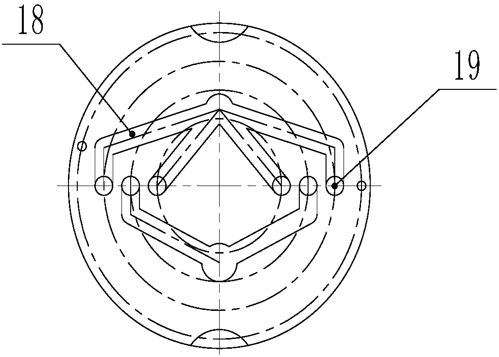
[0058] use as Figure 6 For the boss structure shown, 20D / 4f trefoil-shaped PET conductive fibers are spun, and PET slices with a viscosity of 0.67g / dl are used. The conductive masterbatch is polyester conductive masterbatch from Suzhou Baoli Plastic Materials Co., Ltd., with a melting point of 235°C. The melt index is 100 g / 10 min (265°C, 5 kg bar). The circular hole passes through the PET melt, and the groove passes through the conductive melt.
[0059] Use two screw extruders to melt and transport the dried 80 kg non-conductive PET chips and conductive masterbatch respectively. The temperature of each zone of the screw extruder is set as follows:
[0060] Conveying conductive melt screw: 220°C, 250°C, 256°C, 260°C, 260°C
[0061] Screw conveying PET melt: 250°C, 275°C, 288°C, 288°C, 288°C
[0062] Chamber temperature: 289°C
[0063] After the melts are accurately metered by their own metering pumps, they enter the trilobal composite spinning assembly in a certain propor...
Embodiment 2
[0066] As in the slicing and spinning conditions of Example 1, changing the diameter of the round hole on the regulating plate to Φ3.3mm significantly improved the spinnability. A 20D / 4f trilobal composite conductive fiber was obtained. Megger resistance is 2.5x10 6 Ω / cm, resistivity 50Ω·cm, fiber strength 2.6cN / dtex, elongation at break 56%.
Embodiment 3
[0068] As in the slicing and spinning conditions of Example 1, the diameter of the round hole on the adjustment plate is changed to Φ3.1mm, and the spinnability is good. A 20D / 4f trilobal composite conductive fiber was obtained. Megger resistance is 2.0x10 6 Ω / cm, resistivity 50Ω·cm, fiber strength 2.75cN / dtex, elongation at break 50%.
[0069] The effect of adjusting the diameter of the round hole on the plate on the spinning parameters is as follows:
[0070]
[0071] Through the examples, it can be found that changing the diameter of the circular hole on the adjusting plate can effectively change the spinning parameters of the composite spinning, change the composite performance of the two melts and the uniformity of the composite conductive fiber, and achieve the purpose of the present invention.
PUM
| Property | Measurement | Unit |
|---|---|---|
| Melting point | aaaaa | aaaaa |
| Melt index | aaaaa | aaaaa |
| Resistivity | aaaaa | aaaaa |
Abstract
Description
Claims
Application Information
 - R&D
- Intellectual Property
- Life Sciences
- Materials
- Tech Scout
- Unparalleled Data Quality
- Higher Quality Content
- 60% Fewer Hallucinations
Browse by: Latest US Patents, China's latest patents, Technical Efficacy Thesaurus, Application Domain, Technology Topic, Popular Technical Reports.
© 2025 PatSnap. All rights reserved.Legal|Privacy policy|Modern Slavery Act Transparency Statement|Sitemap|About US| Contact US: help@patsnap.com