Pneumatic turbine driven double rotor test bench

A technology of aerodynamic turbines and test benches, which is used in engine testing, mechanical component testing, and machine/structural component testing. performance, ease of maintenance, and reduced complexity

Active Publication Date: 2018-09-11
BEIJING UNIV OF CHEM TECH
View PDF5 Cites 27 Cited by
  • Summary
  • Abstract
  • Description
  • Claims
  • Application Information

AI Technical Summary

Problems solved by technology

[0006] The dynamic characteristics of the dual-rotor support system coupled through inter-shaft bearings are quite different from those of the single-rotor system. However, the existing test equipment for the dynamic characteristics of the rotor system is usually designed for the single-rotor system, and it is impossible to test the dynamic characteristics of the dual-rotor structure. Research

Method used


Image

  • Pneumatic turbine driven double rotor test bench
  • Pneumatic turbine driven double rotor test bench
  • Pneumatic turbine driven double rotor test bench

Examples


Embodiment Construction

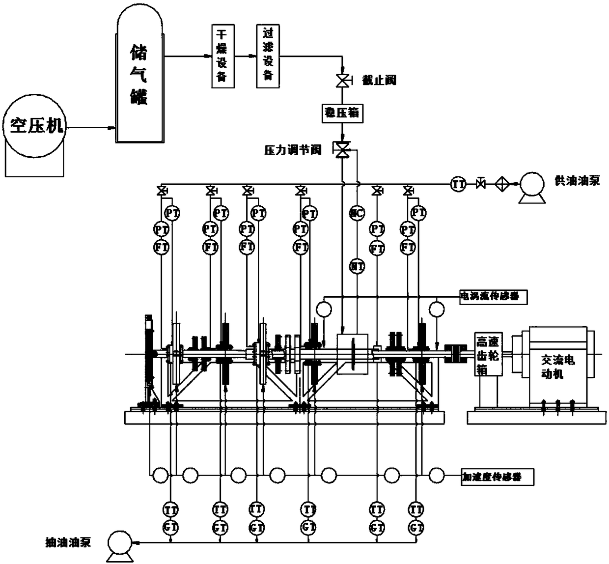
[0043] Operation of the present invention will be further described below in conjunction with accompanying drawing, content of the present invention comprises a complete set of pneumatic turbine type double-rotor test bench system:

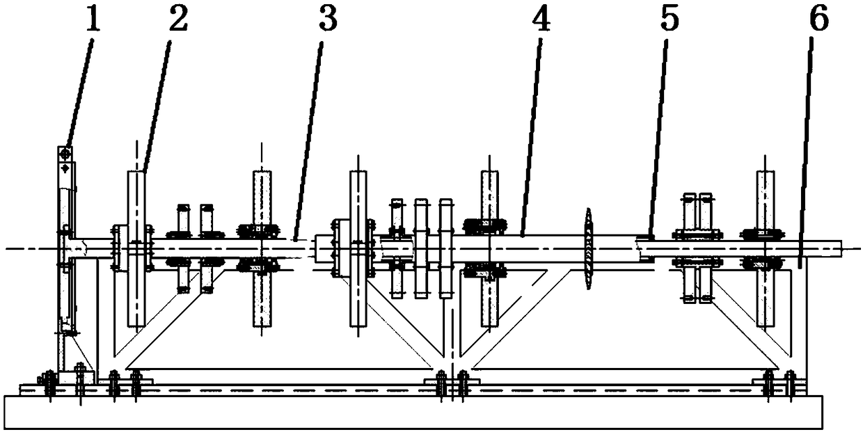
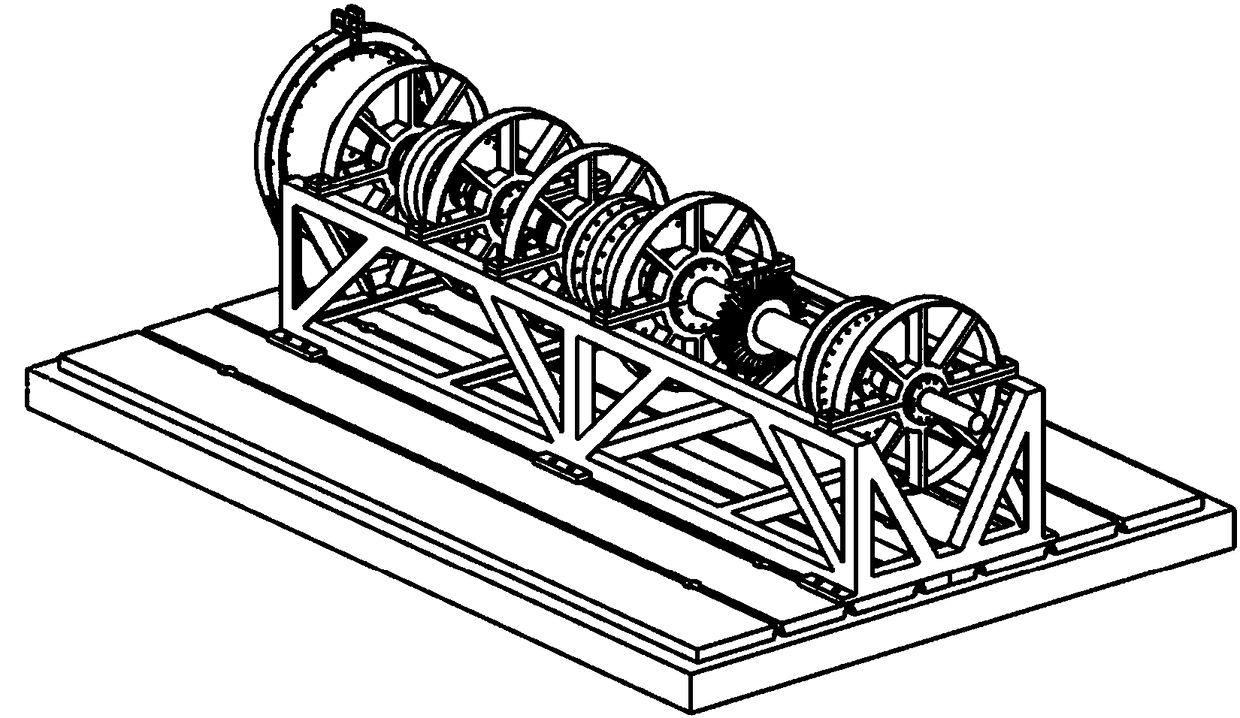
[0044] as attached figure 1 , the inner rotor 3 drive system includes an AC motor and a high-speed gearbox, and the AC motor drives the inner rotor to rotate at high speed through the high-speed gearbox. A small inertia AC motor is selected to improve the response speed of the inner rotor speed control system, and the AC motor is controlled by an ABB frequency converter. The outer rotor 4 is driven by a pneumatic turbine. The driving system includes an air compressor unit and supporting pipelines, air filtration, drying treatment equipment and an air conditioning unit (valve group) for precise flow adjustment, which is driven by compressed air and installed on the outer rotor 4. The high-pressure pneumatic turbine 13 on the top controls and adjus...


PUM


Abstract

The invention discloses a pneumatic turbine driven test bench. The pneumatic turbine driven test bench comprises a rotor system, a power system, a lubrication system, a test system and a safety system. An intermediate bearing is arranged between an inner rotor and an outer rotor; the outer rotor is driven by a pneumatic turbine; a control system is a feedback control system; compressed air drivesthe pneumatic turbine mounted on the outer rotor to rotate. After the compressed air provided by an air compressor enters a pressure stabilizing box, the compressed air flows through a pressure regulating valve and then flows out of a nozzle to impact the pneumatic turbine to drive the pneumatic turbine to rotate; the rotation speed of the outer rotor is detected by a rotation speed transmitter, and then the rotation speed is fed back to a rotation speed controller; the compressed gas flow is adjusted by controlling the opening of the pressure regulating valve to control the rotation speed ofthe outer rotor. In a supporting structure, squirrel cage elastic supports and elastic ring squeeze film dampers are combined, so that the stability of the rotors can be improved. The pneumatic turbine driven test bench can be used for the experimental study of the dynamic characteristics of the double rotor-support system with the coupling of the inner and outer rotors and the simulation and research of the rotor system vibration faults.

Description

technical field [0001] The invention relates to a pneumatic turbine-driven double-rotor test bench, which belongs to the technical field of rotor dynamics test. Background technique [0002] An aero engine is a very complex and precise thermodynamic machine. It is called the heart of the aircraft, which determines the performance, reliability and economy of the aircraft. Because the structure of the aero-engine is very complex and difficult to maintain, it is very prone to failure. Many aircraft accidents are caused by the failure of the aero-engine. A large part of the engine failure is caused by the vibration of the engine rotor. Studies have shown that the excitation source formed by the high-speed rotation of the engine rotor is an important reason for the vibration of the entire engine. A very important link in the engine development process. [0003] Experimental research is a very important auxiliary means in the research process of the vibration fault of the rotor...

Claims


Application Information

Patent Timeline
Patent Type & Authority Applications(China)
IPC IPC(8): G01M15/00G01M13/00
CPCG01M13/00G01M15/00
Inventor 王维民李维博张旭龙陈康
Owner BEIJING UNIV OF CHEM TECH
Why Eureka
Try Eureka