Ship-based radar radome and manufacturing method thereof

A radar radome and manufacturing method technology, applied to antennas, antenna components, antennas suitable for movable objects, etc., can solve the problem of poor wave penetration performance in high and wide frequency bands, short service life cycle, poor waterproof performance, etc. problems, to achieve the effect of improving uniformity, reducing total weight, and reducing resin consumption

Active Publication Date: 2018-09-11
HARBIN TOPFRP COMPOSITE
View PDF9 Cites 18 Cited by
  • Summary
  • Abstract
  • Description
  • Claims
  • Application Information

AI Technical Summary

Problems solved by technology

[0005] The present invention aims to solve many problems such as heavy weight, poor waterproof performance, poor high and wide frequency band wave transmission performance, many internal interlayer bonding defects, weak surface hydrophobicity and mold resistance, and short service life of the assembled structure radome formed by the traditional process. question

Method used


Image

  • Ship-based radar radome and manufacturing method thereof
  • Ship-based radar radome and manufacturing method thereof
  • Ship-based radar radome and manufacturing method thereof

Examples


specific Embodiment approach 1

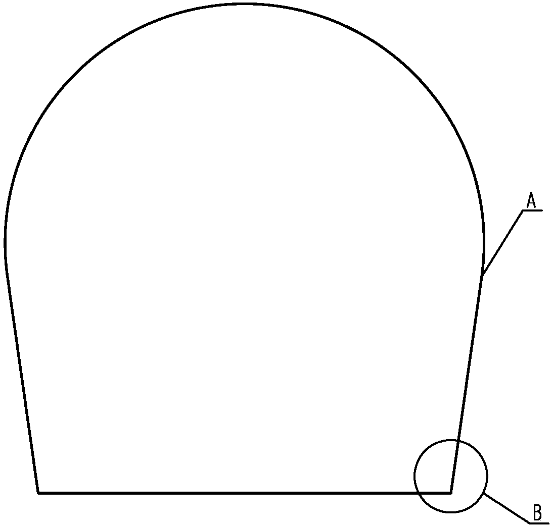
[0065] A kind of shipboard radar antenna is a shipboard radome with the overall structure of high and wide frequency band radar. ,Such as figure 2 Shown; during installation, bolts are used to fasten the connection between the flange of the radome and the base;

[0066] The spherical cap on the upper part of the radome and the lower cylinder (or cone) are the radar antenna wave-transparent zone A; the root of the cylinder (or cone) to the connecting flange is a non-wave-transparent structural reinforcement zone B;

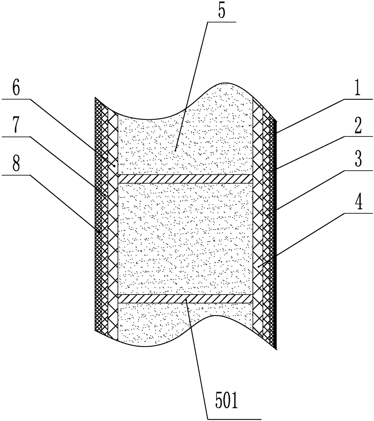
[0067] Such as image 3 As shown, the wave-transmitting area of ​​the radar antenna is a composite material sandwich structure, and the cross-sectional material of the composite material sandwich structure sequentially includes: a super-hydrophobic coating 1, an outer surface wave-transparent paint coating 2, an outer surface Surface anti-aging layer 3, outer skin layer 4, structural foam core layer 5, inner skin layer 6, inner surface wave-transparent paint coa...

specific Embodiment approach 2

[0077] Specific implementation mode two: combining such as Figure 9 To describe this embodiment,

[0078] A method for manufacturing a shipboard radome, comprising the following steps:

[0079] The shape of the molding die D is the same as that of the radome C, and several (set to 4) resin injection ports 101 are evenly distributed on the cylindrical (or conical) edge away from the spherical cap on the molding die having the same shape as the radome. A plurality of (set to 8) resin outlets 102 are uniformly arranged at or near the junction of the spherical cap and the cylinder (or cone) of the molding mold, and several (set to 1) resin outlets 102 are arranged on the top of the spherical crown of the molding mold; The forming mold can be removed in the demoulding step after the product is formed; the forming mold has certain structural rigidity, precise size and shape, perfect sealing, pull-out characteristics and thermal deformation resistance required by product forming; ...

specific Embodiment approach 3

[0107] In the process of laying the outer skin reinforcement transition layer described in this embodiment, the high-strength fiber cloth is laid on the side of the radome wall from the radome connecting flange to the side of the radome wall, and laid until the radome wall is 200mm away from the edge of the flange. That is, the laying height of the transition zone is 200mm, and the laying thickness of the fiber cloth corresponding to the transition zone gradually changes from 4mm to 0.5mm.

[0108] Other steps and parameters are the same as in the second embodiment.


PUM

PropertyMeasurementUnit
Thicknessaaaaaaaaaa
Viscosityaaaaaaaaaa
Thicknessaaaaaaaaaa

Abstract

The present invention provides a ship-based radar radome and a manufacturing method thereof, and relates to a radar radome and a manufacturing method thereof. The objective of the invention is to solve the problems that an assembling structure radome through traditional process forming is heavy in weight and bad in high and wide frequency band wave-transparent performances. The method comprises the steps of: coating resin-based glass flake composite material layer on a forming die as a forming outside surface anti-aging layer; putting a first layer of quartz fibre woven roving at the surface of the solidified resin-based glass flake composite material layer, and putting second, third and fourth layers of quartz fibre woven roving at angles of +-45 degrees and 90 degrees along the seaming with the first layer of quartz fibre woven roving; and putting an exterior skin reinforced transition layer, a form core layer, a skin reinforced transition layer, an internal skin layer and an auxiliary material layer, wherein the auxiliary material layer comprises release cloth, an isolation film, a river diversion net, a resin rapid runner, a first vacuum bag film, a gas conductive mat and a second vacuum bag film. The manufacturing method employs a VRIP (Vacuum Resin Infusion Process) to perform whole and one-step molding, and is used for manufacturing of the radar radome.

Description

technical field [0001] The invention relates to a method for manufacturing a radome. Background technique [0002] The radome, also known as the electromagnetic window, is a protective cover installed outside the radar antenna. Its main purpose is to prevent the influence and interference of the harsh environment on the normal working state of the radar antenna without affecting the radar antenna's transmission or reception of electromagnetic waves, and to ensure that the radar The antenna operates normally around the clock under various working conditions, improving the availability, service life and reliability of the radar antenna, and the comprehensive benefits are very obvious. [0003] In recent years, with the rapid development of China's naval construction and the upgrading of shipboard radar antennas, the demand for radomes for large surface ships is increasing. Compared with the ground radome, the shipborne radome puts forward a series of special requirements, req...

Claims


Application Information

Patent Timeline
IPC IPC(8): H01Q1/42H01Q1/34B29C70/30B29C70/34B29C70/54
CPCB29C70/30B29C70/342B29C70/54H01Q1/34H01Q1/422
Inventor 梅延宁孙宝华潘永生王贵军林敏唐亮孟松于福斌
Owner HARBIN TOPFRP COMPOSITE
Why Eureka
Try Eureka