Clean Textile Machine

A textile machine, clean technology, applied in the field of textile processing, can solve the problems of reduced dust removal efficiency, secondary pollution, blockage of suction devices, etc., and achieve the effects of improving quality, saving costs, and avoiding dust.

Active Publication Date: 2020-01-31
NINGBO WENZE TEXTILE CO LTD
View PDF1 Cites 0 Cited by
  • Summary
  • Abstract
  • Description
  • Claims
  • Application Information

AI Technical Summary

Problems solved by technology

[0004] Although the above-mentioned patent solution solves the deficiencies existing in traditional textile machines, there are still some points to be improved in this solution: 1. In this solution, the air suction device is arranged behind the mesh bag, and the dust is sucked by the air suction device during the dust removal process. On the mesh bag, a small amount of dust may pass through the mesh bag and enter the suction device. Long-term use will easily cause the suction device to be blocked and affect the normal use of the equipment; 2. After collecting the dust on the mesh bag, it is necessary to The dust on the mesh bag is shaken off by vibration, so that the dust falls into the ash hopper. On the one hand, the moving direction of the dust during the shaking off process is uncertain, and it is easy to float in the entire dust removal mechanism, causing secondary pollution. On the one hand, the dust itself is light in weight, and the speed of falling by itself is very slow, resulting in a long time for falling to the ash hopper, resulting in a decrease in the entire dust removal efficiency

Method used


Image

  • Clean Textile Machine
  • Clean Textile Machine

Examples


Embodiment Construction

[0022] The following is further described in detail through specific implementation methods:

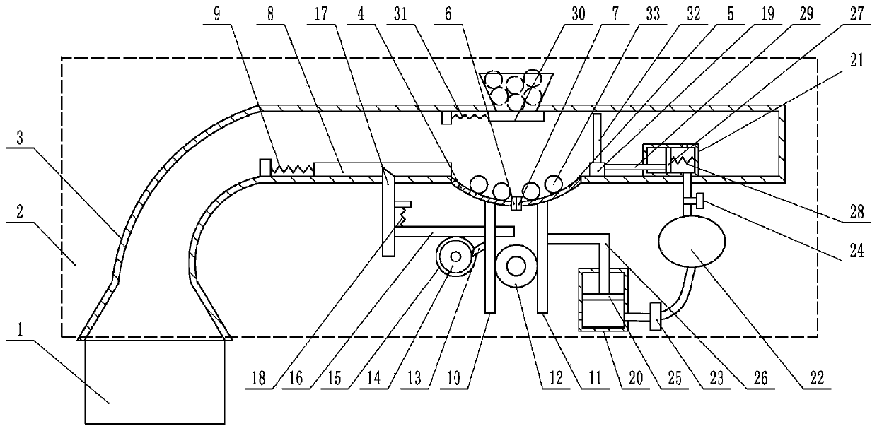
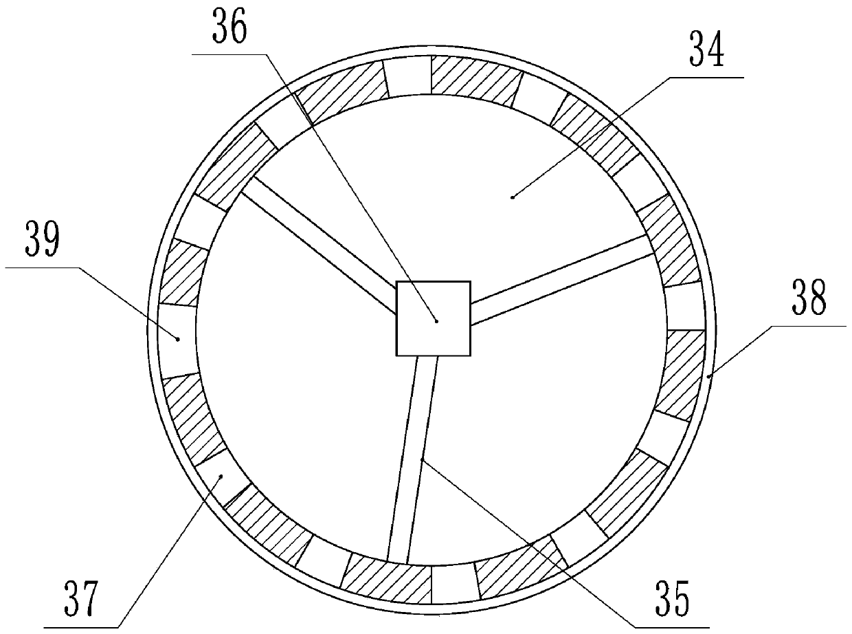
[0023]The reference signs in the drawings of the description include: textile mechanism 1, dust removal mechanism 2, dust delivery pipe 3, first elastic tube 4, second elastic tube 5, first electromagnet 6, second electromagnet 7, flat plate 8, First spring 9, first slide bar 10, second slide bar 11, second gear 12, pawl 13, ratchet 14, first gear 15, rack 16, wedge bar 17, second spring 18, push block 19 , the first piston cylinder 20, the second piston cylinder 21, the air bag 22, the one-way valve 23, the pressure valve 24, the first piston 25, the first piston rod 26, the second piston 27, the fourth spring 28, the second piston rod 29. Baffle plate 30, the third spring 31, push rod 32, dust suction ball 33, cavity 34, support 35, negative pressure fan 36, air inlet 37, sticky dust layer 38, air outlet 39.

[0024] The embodiment is basically as attached figure 1 , figure 2 S...


PUM


Abstract

The invention relates to the technical field of textile processing, and discloses a cleaning type textile machine. The cleaning type textile machine comprises a machine frame, a textile mechanism anda dust removal mechanism; the dust removal mechanism comprises a dust conveying pipe, a feeding port and a discharging port are formed in the dust conveying pipe, the discharging port is connected with a first elastic pipe and a second elastic pipe, a first electromagnet is arranged on the first elastic pipe, and a second electromagnet is arranged on the second elastic pipe; a switch is installedon the dust conveying pipe, a flat plate is connected in the dust conveying pipe in a sliding mode, a first sliding rod and a second sliding rod are connected on the machine frame in a sliding mode, apawl is arranged on the first sliding rod, a ratchet wheel is rotationally connected on the machine frame, the ratchet wheel is coaxially connected with a first gear, the first gear is meshed with arack, a wedge rod is connected on the rack in a sliding mode; a push block and a baffle are connected in the dust conveying pipe in a sliding mode, and a push rod is arranged on the push block; and the dust removal mechanism further comprises a dust suction ball, a hollow cavity is formed in the dust suction ball, a negative pressure fan is arranged in the hollow cavity, the dust suction ball is provided with an air inlet hole, and an ash sticking layer is arranged on the dust suction ball. The textile machine can carry out dust removing efficiently and thoroughly.

Description

technical field [0001] The invention relates to the technical field of textile processing, in particular to a clean textile machine. Background technique [0002] Textile machine is exactly the full name of the tool that the raw material such as thread, silk, fiber crops is processed into silk thread and then is woven into cloth. During the working process of the textile machine, a large amount of dust will appear during the processing of raw materials such as thread, silk, and hemp. If the dust is not collected properly, it is very easy to cause the dust to fly. The negative charge of the negative charge is easily adsorbed on the machine tool or the body of the worker, and even enters the nasal cavity of the human body, causing physical discomfort and seriously damaging human health. Most of the traditional textile machines do not deal with the dust, but the textile workers wear masks to work. The extensive use of masks will not only cause waste, but also inhale more dust ...

Claims


Application Information

Patent Timeline
Patent Type & Authority Patents(China)
IPC IPC(8): B08B15/04B08B15/00
CPCB08B15/007B08B15/04
Inventor 许根海
Owner NINGBO WENZE TEXTILE CO LTD
Why Eureka
Try Eureka