A Welding Manufacturing Process of Aluminum Alloy Cross Beam Composition of EMU

A technology of aluminum alloy beam and manufacturing process, which is applied in the field of welding and manufacturing process of aluminum alloy beams of EMUs, can solve the problems of inability to weld and form, the back space of the welding seam is narrow, and the welding gap cannot be adjusted, etc., so as to ensure the assembly size and welding Seam requirements, prevent the collapse of the welding surface, easy to control and achieve the effect

Active Publication Date: 2021-04-23
QINGDAO LIANCHENG HONGDA RAIL TRAFFIC EQUIP
View PDF6 Cites 0 Cited by
  • Summary
  • Abstract
  • Description
  • Claims
  • Application Information

AI Technical Summary

Problems solved by technology

[0002] The crossbeam composition of the EMU is distributed under the underframe of the EMU car body. Each EMU has several pieces. The design requires that the two ribs must be welded through. Because the welding gap is small, and the ribs cannot move the heavy gap, the welded ribs are only 19-20mm Wide, and both adjacent sides must be welded, the heat-affected zone of the two welds overlaps, and penetration is required, and the current cannot be increased on a conventional basis, which is prone to thermal cracks, and the welding gap cannot be adjusted, and the space behind the weld is narrow , the use of ordinary removable welding backing plate cannot be fixed and cannot be welded into shape, and the penetration without welding backing plate cannot be guaranteed. At that time, the customer had high requirements, and there were hundreds of pieces, and the quality and quantity could not meet the customer's requirements.

Method used


Image

  • A Welding Manufacturing Process of Aluminum Alloy Cross Beam Composition of EMU
  • A Welding Manufacturing Process of Aluminum Alloy Cross Beam Composition of EMU

Examples


Embodiment Construction

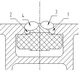
[0021] See attached figure 1 with 2 Shown, the present invention prepares the step of described EMU horizontal composition to be six steps. The first step is to prepare before welding, check the on-site temperature, humidity, shielding gas, welding wire, and whether the performance of the welding machine is good. When the on-site temperature and humidity meet the requirements, conduct the pre-weld welding process test, use an 8mm aluminum plate to weld a weld seam with a length of more than 200mm, and then conduct the welding process test by the welding supervisor; the second step is cleaning and polishing, and the parts are cleaned with a cleaning agent. 1-2 Clean the oil stain within 30mm of the welding area, and then use a mechanical polishing machine to throw away the oxide film at the 20mm of the welding seam; the third step is to assemble the spot welding, and put it in the assembly rib according to the requirements of the drawing Removable welding backing plate, use t...


PUM

PropertyMeasurementUnit
thicknessaaaaaaaaaa
diameteraaaaaaaaaa

Abstract

The invention relates to a welding manufacturing process for the aluminum alloy crossbeam composition of the EMU. The manufacturing process prepares the crossbeam composition for the EMU. The process uses wedge-shaped inclined pads and welding backing plates to weld ribs and product accessories to form an EMU. Composed of a group of beams, the ribs are two cuboid aluminum materials with a thickness of 8mm placed parallel on the product accessories, the welding gap is between 1mm-2mm, using ¢1.2mm aluminum alloy welding wire, using MIG welding, ribs The plate is flush with the upper surface of the product accessories. The welding backing plate is a movable rectangular parallelepiped steel material with a welding gap of 2mm. The welding gap of the movable welding backing plate is greater than or equal to the welding gap of the weld seam. The movable welding backing plate There is a unilateral boss, whose height is slightly higher than the upper surface of the product accessories, which can ensure that the ribs will not collapse after welding; the invention makes difficult welding easy to operate, saving time and shortening the production cycle for mass production shortened, thus greatly improving work efficiency.

Description

technical field [0001] The invention belongs to the field of welding technology, and in particular relates to a welding manufacturing process of an aluminum alloy crossbeam for an EMU. Background technique [0002] The crossbeams of the EMU are distributed under the underframe of the EMU car body. Each EMU has several pieces. The design requires that the two ribs must be welded through. Because the welding gap is small, and the ribs cannot move to increase the gap, the welded ribs are only 19-20mm Wide, and both adjacent sides must be welded, the heat-affected zone of the two welds overlaps, and the weld needs to be penetrated, and the current cannot be increased on a conventional basis, which is prone to thermal cracks, and the welding gap cannot be adjusted, and the space behind the weld is narrow , the use of ordinary removable welding backing plate cannot be fixed and welded into shape, and the penetration without welding backing plate cannot be guaranteed. At that time,...

Claims


Application Information

Patent Timeline
Patent Type & Authority Patents(China)
IPC IPC(8): B23K9/173B23K9/235B23K9/007B23K9/02
CPCB23K9/007B23K9/02B23K9/173B23K9/235
Inventor 刘双剑董建锋
Owner QINGDAO LIANCHENG HONGDA RAIL TRAFFIC EQUIP
Why Eureka
Try Eureka