Tool for polishing ceramic mobile phone back plate

A technology for tooling and mobile phones, which is applied in the field of polishing and processing tooling using vacuum adsorption ceramic mobile phone backplanes, can solve the problems that the edge integrity of the backplane is greatly affected, the processing efficiency and yield are affected, and the loading and unloading time is increased. Scratch effect, reduce loading and unloading time, reduce quantity effect

Pending Publication Date: 2018-09-14
HARBIN AURORA OPTOELECTRONICS TECH
View PDF0 Cites 1 Cited by
  • Summary
  • Abstract
  • Description
  • Claims
  • Application Information

AI Technical Summary

Problems solved by technology

Due to the small thickness of the back plate of the ceramic mobile phone, during the polishing process, the use of traditional tooling for clamping has a great impact on the integrity of the edge of the back plate, and it is easy to pinch the back plate
The use of viscose technology will increase the loading and unloading time, and the workpiece will be broken when unloading, which will affect the overall processing efficiency and yield

Method used


Image

  • Tool for polishing ceramic mobile phone back plate
  • Tool for polishing ceramic mobile phone back plate
  • Tool for polishing ceramic mobile phone back plate

Examples


Embodiment 1

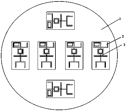
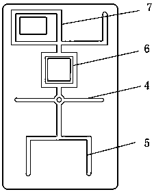
[0027] combine Figure 1-2 , this embodiment includes a bottom surface 1 , a vacuum adsorption tooling 2 and a vacuum adsorption hole 3 . image 3 It is a schematic diagram of the structure of the vacuum adsorption tooling. The middle part of the tooling is the vacuum adsorption hole extending two horizontal air grooves 4 to the sides of the mobile phone. The lower part of the tooling is the adsorption hole extending an air groove to the bottom of the mobile phone. Three equidistant equidistant air grooves 5 . The upper part of the tooling is a vacuum suction hole extending an air groove to the top of the mobile phone, and the upper middle part is set as a square hollow structure, with square air grooves 6 distributed around it, and the four corners of the square are rounded. Three equidistant air grooves are extended on the top of the square structure, of which the left air groove is connected to the rectangular hollow structure, and square air grooves 7 are distributed arou...

Embodiment 2

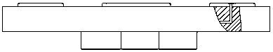
[0034] Embodiment 2: In this embodiment, the bottom surface is disc-shaped, with a diameter of 500mm and a height of 30mm, and a device connected to the polishing machine is provided at the bottom. Six through holes are distributed in the disk, and the vacuum adsorption hole of the machine tool is connected with the six through holes in the disk.

[0035] The vacuum adsorption tooling is a rectangular sheet structure with a length of 150mm, a width of 66mm and a height of 6.5mm. The groove width of the air groove is 4.5mm, the depth is 6.5mm, and the distance between the two grooves is 25mm. The ends of each air groove are rounded, and the radius of the rounded corners is 2mm. Square hollow structure The side length of the square is 12.5mm, and the height is 6.5mm consistent with the vacuum adsorption tooling. The four corners of the square hollow structure are rounded. Remove the tooling material in this area and set it as a hollow structure. Rectangular hollow structure ...


PUM

PropertyMeasurementUnit
Diameteraaaaaaaaaa
Heightaaaaaaaaaa
Heightaaaaaaaaaa

Abstract

The invention relates to a tool for polishing a ceramic mobile phone back plate. The tool comprises a bottom surface, vacuum adsorption tool bodies and vacuum adsorption holes. The tool adopts a special groove type and a special material, in the mobile phone back plate machining process, the clamping precision of the mobile phone back plate can be guaranteed, the machining precision of the mobilephone back plate can be improved, the yield of the mobile phone back plate can be increased, in addition, the scratching effect of an acrylic material or an aluminum alloy material on the ceramic mobile phone back plate can be reduced by using the material, and secondary damage in the machining process can be reduced. The tool has the advantages that the adsorption force is strong, the number of the vacuum air grooves can be decreased, and meanwhile the comprehensive cost of the tool can be lowered.

Description

technical field [0001] The invention relates to a tool for polishing, in particular to a tool for polishing the back plate of a ceramic mobile phone using vacuum adsorption. Background technique [0002] Zirconia ceramic materials have high strength and high hardness, and have the advantages of high temperature resistance, corrosion resistance, and low shielding signal effect. They have become a new type of civil material and are gradually used in the preparation of electronic products. application on the housing. Due to the small thickness of the back plate of the ceramic mobile phone, during the polishing process, the use of traditional tooling for clamping has a great impact on the integrity of the edge of the back plate, and it is easy to pinch the back plate. The use of viscose technology will increase the loading and unloading time, and the workpiece will be broken when unloading, which will affect the overall processing efficiency and yield rate. Therefore, in order...

Claims


Application Information

Patent Timeline
IPC IPC(8): B24B19/00B24B29/02B24B41/06
CPCB24B19/008B24B29/02B24B41/06
Inventor 左洪波杨鑫宏李铁袁帅
Owner HARBIN AURORA OPTOELECTRONICS TECH
Why Eureka
Try Eureka