

Rubber pipe molding device
A molding device and rubber tube technology, applied in the direction of tubular articles, other household appliances, household appliances, etc., can solve the problems of easy wear of the inner wall of the rubber tube, high friction, stretching and deformation of the rubber tube, etc., and reduce the friction force. , The effect of reducing tension and improving production efficiency
Active Publication Date: 2018-09-14
宁波高新区新柯保汽车科技有限公司
View PDF4 Cites 0 Cited by
- Summary
- Abstract
- Description
- Claims
- Application Information
AI Technical Summary
Problems solved by technology
In order to force the shaped rubber tube to leave the mold, it is necessary to continuously pull the rubber tube toward the discharge end. However, since the inner wall of the rubber tube is in contact with the mold core, the friction force on the rubber tube is relatively large during this process, and pulling the rubber tube is also necessary. Larger pulling force is required, so the rubber tube is easily stretched and deformed
Secondly, the rubber tube slides relative to the mold core, and the inner wall of the rubber tube is easily worn
Method used
View moreImage
Smart ImageViewing Examples

Examples
Embodiment Construction
[0019] Below in conjunction with accompanying drawing and specific embodiment the present invention will be described in further detail:
Login to View More PUM
 Abstract
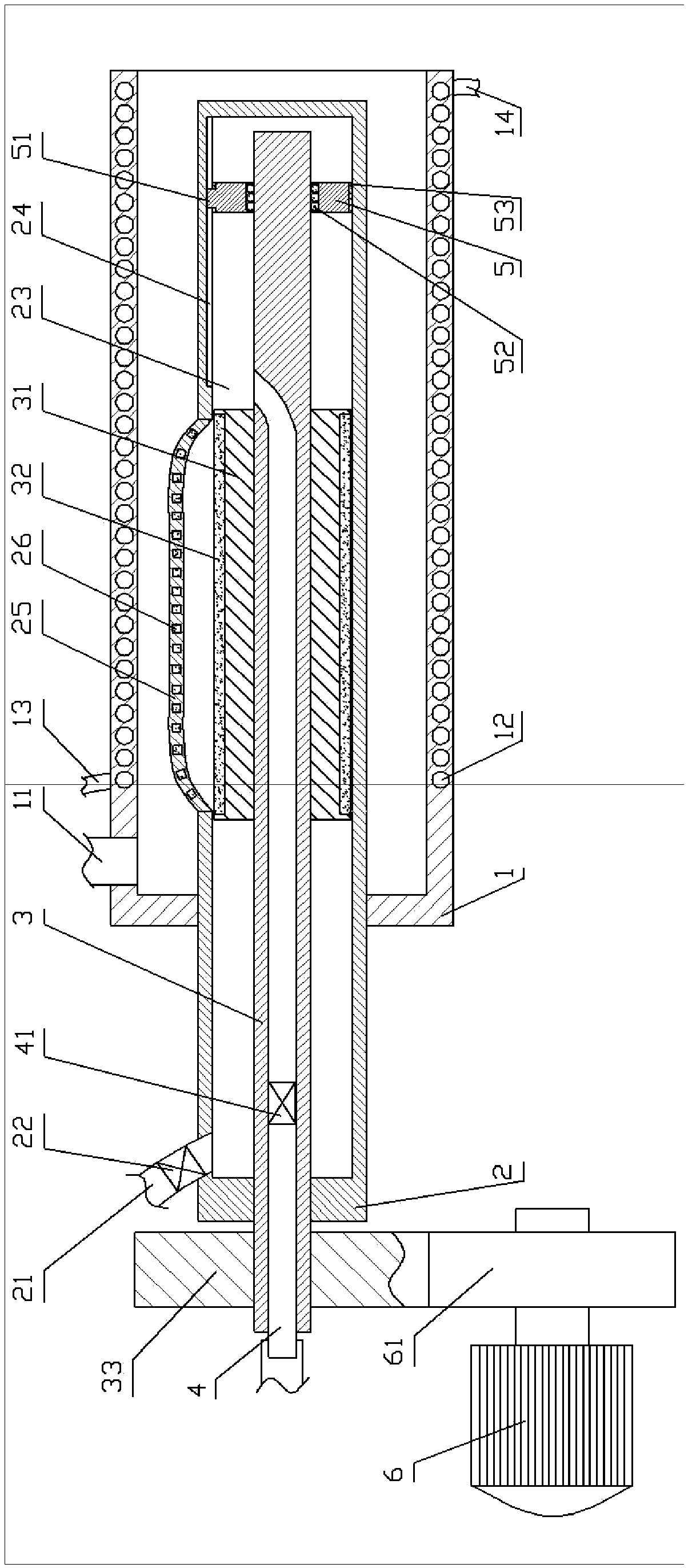
The invention relates to the field of rubber, and particularly discloses a rubber pipe molding device which comprises a framework, a stepper motor, an extrusion pipe and a core mechanism. A feed pipeis fixed onto the extrusion pipe; the core mechanism comprises an inner rod, a rotary shaft, a liquid inlet pipe, a liquid outlet pipe and a piston, the inner rod can be driven by the stepper motor torotate, an accommodating cavity is arranged in the inner rod, openings are formed in the side walls of the accommodating cavity, elastic sheets are arranged outside the openings and are fixed to theouter wall of the inner rod, first magnets are embedded in the elastic sheets, and second magnets are fixed onto the rotary shaft; the piston is positioned in the accommodating cavity and is in threadfit with the rotary shaft, balls are arranged between the piston and the rotary shaft, a slide groove is formed in the side walls of the accommodating cavity, and a slider is fixed onto the piston; aliquid inlet check valve and a liquid outlet check valve are fixed into the liquid inlet pipe and the liquid outlet pipe, and the liquid inlet pipe and the liquid outlet pipe are communicated with the accommodating cavity. According to the scheme, the rubber pipe molding device has the advantages that tensile force required for pulling rubber pipes can be reduced, and the rubber pipes can be prevented from being dragged to deform.
Description
technical field [0001] The invention relates to the field of rubber, in particular to the field of rubber tube molding. Background technique [0002] The rubber tube is resistant to ultraviolet light, ozone, high and low temperature (-80 to 300 degrees), high transparency, strong resilience, compression resistance, oil resistance, stamping resistance, acid and alkali resistance, wear resistance, flame retardant, voltage resistance, conductivity, etc. Performance, suitable for various harsh working environments, the production of rubber tubes has also been greatly developed. [0003] At present, the commonly used rubber tube molding equipment is an extrusion device, which heats the rubber raw material to a molten state, then uses a special extrusion device to extrude it, and then cools and cuts it. Because the cross-section of the rubber tube is circular, the extrusion device generally includes a cylindrical mold on the periphery and a cylindrical mold core inside the mold. ...
Claims
Login to View More Application Information
Patent Timeline
 IPC IPC(8): B29C47/88B29L23/00
CPCB29C48/09B29C48/9115B29L2023/22
Inventor王作栋
Owner宁波高新区新柯保汽车科技有限公司