
Self-driving new energy vehicle

A new energy vehicle, autonomous driving technology, applied in electric vehicles, electric vehicle charging technology, motor vehicles, etc., can solve the problems of unsuitable charging requirements for autonomous vehicles, occupation, waste of time, etc.

Active Publication Date: 2018-09-18
朱幕松
View PDF6 Cites 1 Cited by
  • Summary
  • Abstract
  • Description
  • Claims
  • Application Information

AI Technical Summary

Problems solved by technology

[0002] At present, all countries in the world are actively developing self-driving cars. my country's self-driving cars have achieved new technological breakthroughs in complex environment recognition, intelligent behavior decision-making and intelligent control, and have reached the world's advanced level. In order to save energy and protect the environment, the existing self-driving cars Cars are preferred to use new energy vehicles, but the charging problem has always been the main obstacle to the development of new energy vehicles. At present, new energy vehicles mainly rely on extensive charging piles for charging. However, charging piles cannot store a large amount of electric energy for the battery in a short period of time, and require manual operation. Connecting the charger to the car battery results in car charging not only occupying space, but also inconvenient to charge and a waste of time, so it is not suitable for the charging requirements of self-driving cars

Method used


Image

  • Self-driving new energy vehicle
  • Self-driving new energy vehicle
  • Self-driving new energy vehicle

Examples


Embodiment Construction

[0017] Further description will be made below in conjunction with accompanying drawings.

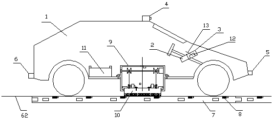
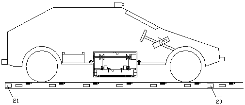
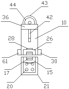
[0018] exist figure 1In the schematic diagram of the overall structure of the self-driving new energy vehicle coupled and charging state shown in the right view, the self-driving new energy vehicle uses any type of pure electric vehicle 1, and the instrument panel in the front cab of the pure electric vehicle is equipped with a GPS satellite positioning system 2 And computer control system 3, the computer control system is equipped with an intelligent control module and an intelligent charging module, the top of the pure electric vehicle is equipped with a recognition camera 4, the front end of the pure electric vehicle is equipped with a front left laser radar and a front right laser radar 5, and the rear end is equipped with a rear left Laser radar and rear right laser radar 6, described GPS satellite positioning system is connected with described computer control system, and described...


PUM


Abstract

The invention provides a self-driving new energy vehicle. Both driving and charging of the self-driving new energy vehicle are automatic; the upper end of a long-distance white guide rail is consistent with a pavement; the long-distance white guide rail does not occupy the pavement, does not affect the traffic and does not affect the appearance of a city; during running of the vehicle, a sub-edgepower receiving plate and the long-distance white guide rail carry out intermediate frequency radio transmission in electromagnetic induction in a continuous and dynamic closed magnetic flux state, the electromagnetic radiation is small, and the transmission efficiency is high; the sub-edge power receiving plate is in non-contact coupling at the upper end of the long-distance white guide rail carry so that friction loss does not exist; the sub-edge power receiving plate automatically finds the long-distance white guide rail; an intelligent control module accurately controls the sub-edge powerreceiving plate to be always kept in the white guide rail; the horizontal angle and left and right positions of the sub-edge power receiving plate are automatically adjusted in a cabinet; the sub-edgepower receiving plate and the long-distance white guide rail are coupled to be automatically positioned; when the vehicle drifts off the lane beyond a range on the left and on the right, the sub-edgepower receiving plate is automatically recovered; six long-distance white guide rails of a city road become a city road charging field; and the charging field automatically recognizes and supplies power to each vehicle and reasonably charges each vehicle.

Description

technical field [0001] The invention relates to an automatic driving vehicle, to be precise, an automatic driving new energy vehicle. Background technique [0002] At present, all countries in the world are actively developing self-driving cars. my country's self-driving cars have achieved new technological breakthroughs in complex environment recognition, intelligent behavior decision-making and intelligent control, and have reached the world's advanced level. In order to save energy and protect the environment, the existing self-driving cars Cars are preferred to use new energy vehicles, but the charging problem has always been the main obstacle to the development of new energy vehicles. At present, new energy vehicles mainly rely on extensive charging piles for charging. However, charging piles cannot store a large amount of electric energy for the battery in a short period of time, and require manual operation. Connecting the charger to the car battery results in a car cha...

Claims


Application Information

Patent Timeline
IPC IPC(8): B60L11/18G05D1/02G05D1/00
CPCG05D1/0005G05D1/0011G05D1/0088G05D1/0225G05D1/0248G05D1/0257G05D1/0278B60L53/12Y02T10/70Y02T90/16Y02T90/12Y02T10/7072Y02T90/14
Inventor 朱幕松
Owner 朱幕松
Learn More