
A device for suppressing pressure pulsation of jet source of centrifugal pump

A technology of pressure pulsation and centrifugal pumps, which is applied to components, pumps, and pump components of pumping devices for elastic fluids, and can solve the problems of not suppressing the pressure pulsation of the jet source of the centrifugal pump, the large flow resistance of the rubber surface, and the like. Consumption of centrifugal pump power and other issues to achieve the effect of improving anti-cavitation ability, good flow regulation ability, and inhibiting separation

Active Publication Date: 2019-09-27
HARBIN ENG UNIV
View PDF6 Cites 0 Cited by
  • Summary
  • Abstract
  • Description
  • Claims
  • Application Information

AI Technical Summary

Problems solved by technology

The problem of this structure in actual use is: the surface flow resistance of the rubber is large, and when multiple combinations are used, the flow resistance of the pipeline will increase, thereby consuming the power of the centrifugal pump and causing the flow velocity in the pipeline to decrease.
However, when using this energy storage device, it is necessary to set different initial inflation pressures according to the position of the accumulator, and at the same time, multiple accumulators in different positions must be used together to achieve good results. Therefore, the device is used in actual use. more cumbersome
[0005] In summary, there is no better device for suppressing the pressure pulsation of the jet source of the centrifugal pump

Method used


Image

  • A device for suppressing pressure pulsation of jet source of centrifugal pump
  • A device for suppressing pressure pulsation of jet source of centrifugal pump
  • A device for suppressing pressure pulsation of jet source of centrifugal pump

Examples


Embodiment Construction

[0027] The present invention will be further described in detail below in conjunction with the accompanying drawings and specific embodiments.

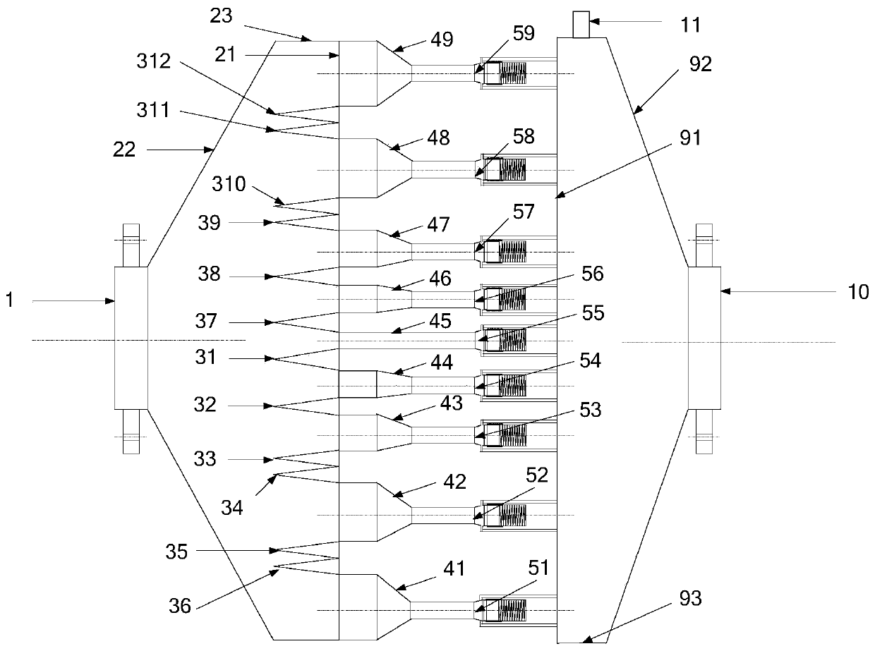
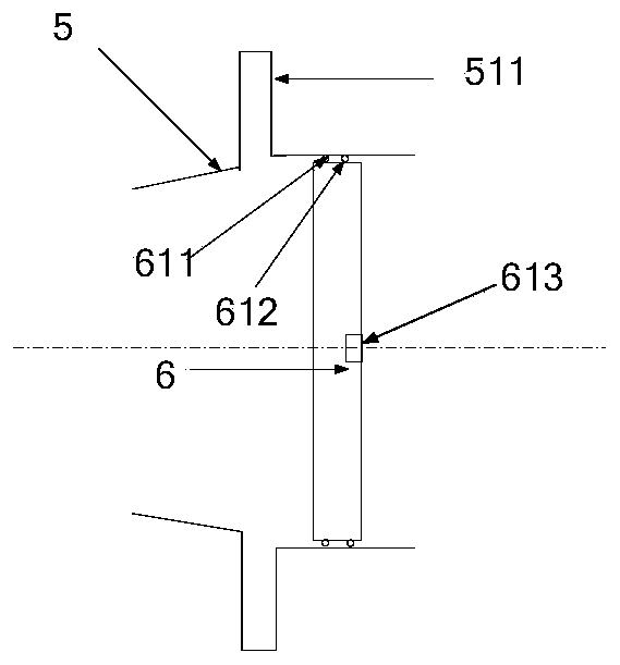
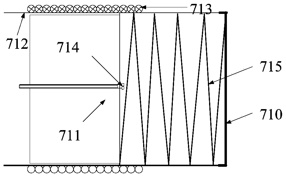
[0028] to combine Figure 1 to Figure 6 , the present invention provides a device for suppressing the pressure pulsation of the jet source of a centrifugal pump, which includes a first flange 1, a first reducing pipe 2, a decompression cone, a first branch pipe 4, a sealing head 5, a piston 6, and an electromagnetic damper 7. The second branch pipe 8, the second reducing pipe 9, the second flange 10, the air release valve 11, the first flange 1 is connected to the first reducing pipe 2, and the decompression cone is installed on the first reducing pipe 2 On the base 21 of the first branch pipe 4, one end of the first branch pipe 4 is connected to the first reducing pipe 2, the other end of the first branch pipe 4 is connected to the head 5, the piston 6 is placed in the head 5, and one end of the piston 6 is connected to the electroma...


PUM


Abstract

The invention provides a device for inhibiting pressure pulsation of a jet source of a centrifugal pump. The device comprises a first flange, a first reducing tube, a reducing cone, a first branch pipe, a seal head, a piston, an electromagnetic damper, a second branch pipe, a second reducing pipe and a second flange, wherein the first flange is connected to the first reducing pipe, the reducing cone is mounted at the bottom end of the first reducing pipe, the other end of the first reducing pipe is connected to the first branch pipe, the first branch pipe is connected to the seal head, the piston is placed in the seal head, the electromagnetic damper is mounted at the other end of the seal head, one end of the second branch pipe is connected to the seal head while the other end of the second branch pipe is connected to the second reducing pipe, and the other end of the second reducing pipe is connected to the second flange. The device for inhibiting pressure pulsation of the jet sourceof the centrifugal pump converts kinetic energy caused by pressure pulsation into heat energy by means of the electromagnetic damper and the piston mechanism to be absorbed by a water medium in a pipeline, so that the pressure pulsation of the jet source of the centrifugal pump is eliminated. Compared with a shock absorber throat and a stainless steel joint made from rubber, the device has a certain flow adjusting and stabilizing capacity.

Description

technical field [0001] The invention relates to a device for suppressing the pressure pulsation of a jet source of a centrifugal pump, which belongs to the field of acoustic measurement. Background technique [0002] In the measurement process of pipeline radiation noise with water as the transmission medium, vertical centrifugal pumps are often used as the propulsion equipment for the fluid in the pipeline, that is, the jet source. Vertical centrifugal pumps, submersible pumps, etc. are all pump bodies constructed with motors. During the process of water absorption and drainage, the periodic rotation of the impeller will generate periodic pressure pulsations in the pipeline, and the pressure pulsations will generate sound waves, thereby The hydrophone in the pipeline receives single-frequency and double-frequency line spectrum noise. The signal amplitude of this radiated noise is extremely large, which is a great method for studying the jet noise of the water-filled pipelin...

Claims


Application Information

Patent Timeline
Patent Type & Authority Patents(China)
IPC IPC(8): F04D29/66F04D29/68
Inventor 刘永伟姜虹旭牛晨商德江
Owner HARBIN ENG UNIV
Learn More