
Automatic cutting device and automatic cutting equipment

An automatic cutting device and cutting technology, applied in metal processing and other directions, can solve the problems of low utilization rate of material tape, low cutting efficiency, and high cutting cost, so as to improve cutting efficiency, save cutting process, reduce The effect of cutting costs

Pending Publication Date: 2018-09-21
温岭市六菱机械有限公司
View PDF6 Cites 6 Cited by
  • Summary
  • Abstract
  • Description
  • Claims
  • Application Information

AI Technical Summary

Problems solved by technology

[0004] The purpose of the present invention is to provide an automatic cutting device and automatic cutting equipment, to alleviate the cutting equipment in the prior art that requires manual participation, resulting in low cutting efficiency, low utilization rate of material tape, and high cutting cost. technical problem

Method used


Image

  • Automatic cutting device and automatic cutting equipment
  • Automatic cutting device and automatic cutting equipment
  • Automatic cutting device and automatic cutting equipment

Examples


Embodiment 1

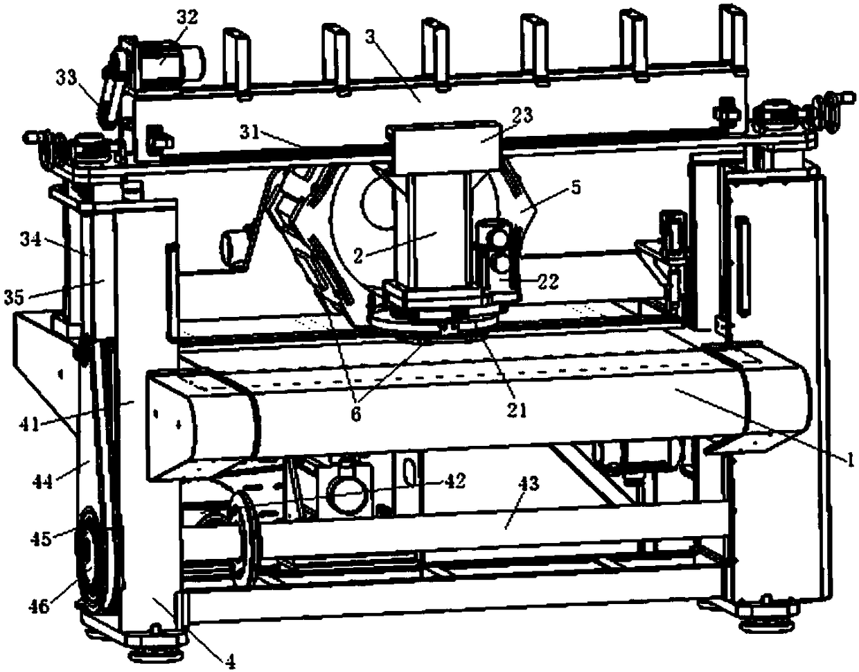
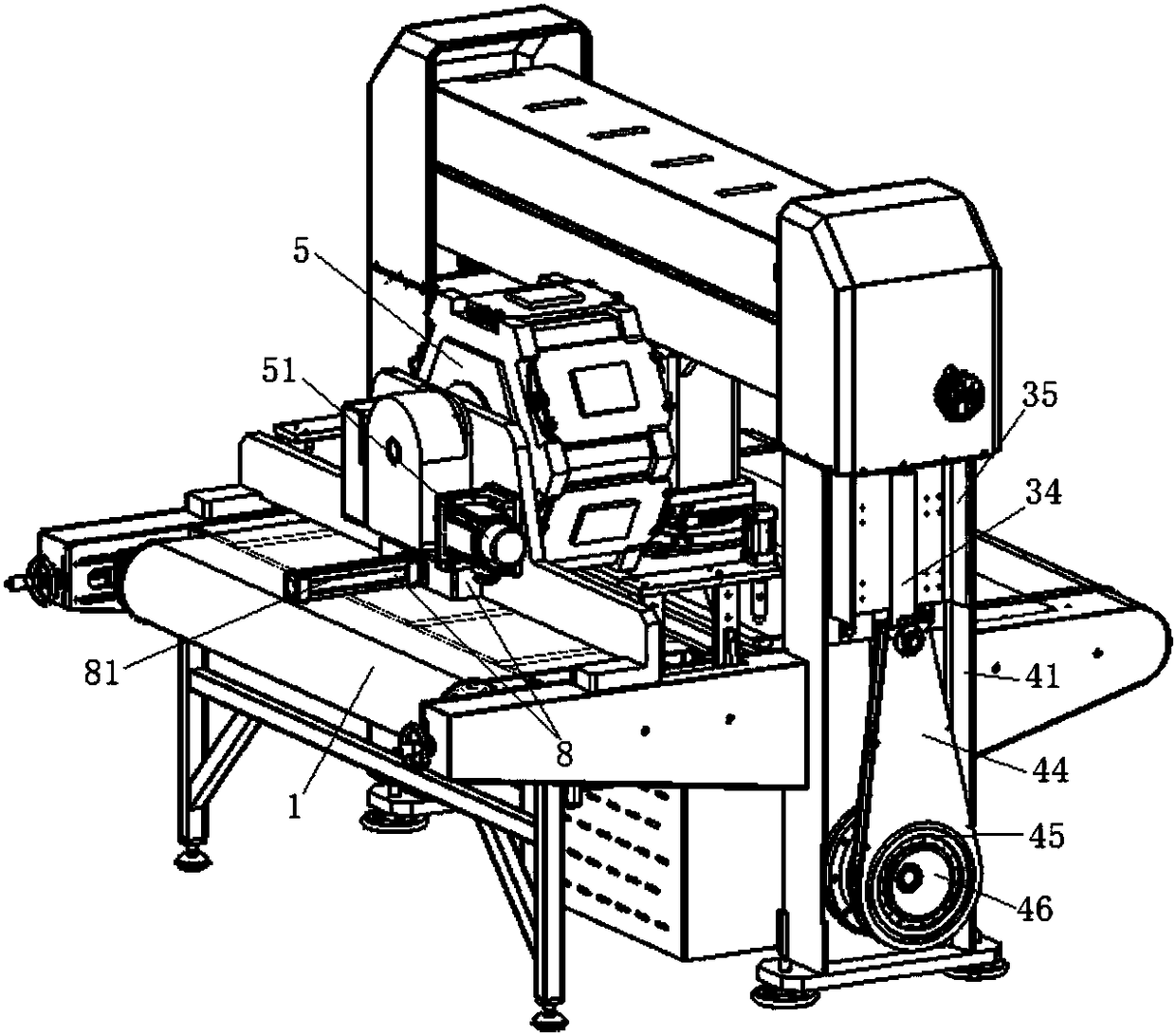
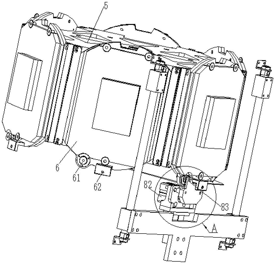
[0038] Such as figure 1 with figure 2As shown, the embodiment of the present invention provides an automatic cutting device, including a conveyor belt 1 for carrying and conveying the material to be cut, a cutting seat 2 capable of installing a knife 6, and controlling the cutting seat 2 to carry out a process on the material to be cut once. Horizontal cutting movement mechanism; the material to be cut is placed horizontally on the conveyor belt 1, the length direction of the material to be cut is the same as the horizontal conveying direction of the conveyor belt 1, and the cutting seat 2 is fixed on the movement mechanism and located above the conveyor belt 1, The conveyor belt 1 can move periodically while the movement mechanism is working.

[0039] The automatic cutting device provided by the embodiment of the present invention includes a conveyor belt 1, a cutting seat 2 and a moving mechanism, wherein the conveyor belt 1 is used to replace the fixed cutting table to ca...

Embodiment 2

[0063] An embodiment of the present invention provides an automatic cutting device, including the automatic cutting device as described above.

[0064] On the basis of the automatic cutting device, the automatic cutting equipment can also be provided with a tray with materials to be cut and a receiving station for receiving finished products. The tray and the receiving station can be arranged at both ends of the conveyor belt 1 respectively.

[0065]When the automatic cutting equipment provided by the present embodiment works specifically, at first the movable end of the material to be cut on the tray is flattened on the conveyor belt 1, and the corresponding cutter 6 is installed on the cutting seat 2, and then the program is set. Under the premise that the movement mechanism and the cutting seat 2 work, the finished product of the specified shape is cut out on the material to be cut, until the material to be cut is cut in the lateral area of ​​the material to be cut, and the ...


PUM


Abstract

The invention provides an automatic cutting device and automatic cutting equipment and relates to the technical field of shoe, clothe, bag and luggage industries. The automatic cutting device comprises a conveyer belt used for bearing and conveying materials to be cut, a cutting seat and a movement mechanism, wherein cutters can be installed on the cutting seat, the movement mechanism controls thecutting seat to conduct transverse cutting on the materials to-be-cut once. The materials to be cut are horizontally placed on the conveyer belt, and the length direction of the materials to be cut is identical with the horizontal conveying direction of the conveyer belt. The cutting seat is fixed to the movement mechanism and located above the conveyer belt. The conveyer belt can conduct periodical movement when the moment mechanisms work. The automatic cutting device and the automatic cutting equipment relieve the technological problems that in the prior art, cutting equipment needs manualintervention, so that the cutting efficiency is low, the utilization rate of a material strip is low, and the cutting cost is high.

Description

technical field [0001] The present invention relates to the technical field of cutting equipment, in particular to an automatic cutting device and automatic cutting equipment. Background technique [0002] The automatic cutting machine is used for the division and cutting of sheets in all walks of life. It does not need any molds; it is controlled by the system software, and then directly cuts the product, as long as the corresponding parameters are set on the operating platform, The computer transmits corresponding instructions to the cutting machine; the cutting machine quickly cuts according to the accepted design drawings, with high automation procedures and simple operation. It is the cutting equipment used in many industries at present. [0003] A cutting method adopted at the present stage is to use the cutting seat equipped with a cutting knife to reciprocate only in the transverse direction of the cutting table after setting the cutting table to cut the material ta...

Claims


Application Information

Patent Timeline
IPC IPC(8): B26F1/38B26D7/06B26D7/26
CPCB26D7/0625B26D7/2614B26F1/38
Inventor 侯飞
Owner 温岭市六菱机械有限公司
Learn More