Machining center tool failure preventing system

A fault prevention, machining center technology, applied in wood processing appliances, manufacturing tools, circular saws, etc., can solve the problem of not being able to prevent tool wear and chip removal in time, and achieve the purpose of preventing wear, increasing gas discharge, and improving grinding effect. Effect

Inactive Publication Date: 2018-09-21
INST OF LASER & OPTOELECTRONICS INTELLIGENT MFG WENZHOU UNIV
View PDF6 Cites 8 Cited by
  • Summary
  • Abstract
  • Description
  • Claims
  • Application Information

AI Technical Summary

Problems solved by technology

[0004] The present invention intends to provide a tool failure prevention system for machining centers to solve the problem that tool wear and chip removal cannot be prevented in time when cutting wood

Method used


Image

  • Machining center tool failure preventing system
  • Machining center tool failure preventing system
  • Machining center tool failure preventing system

Examples


Embodiment Construction

[0024] The following is further described in detail through specific implementation methods:

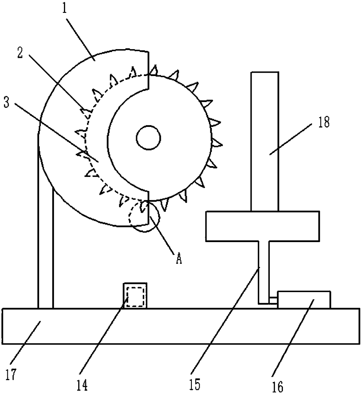
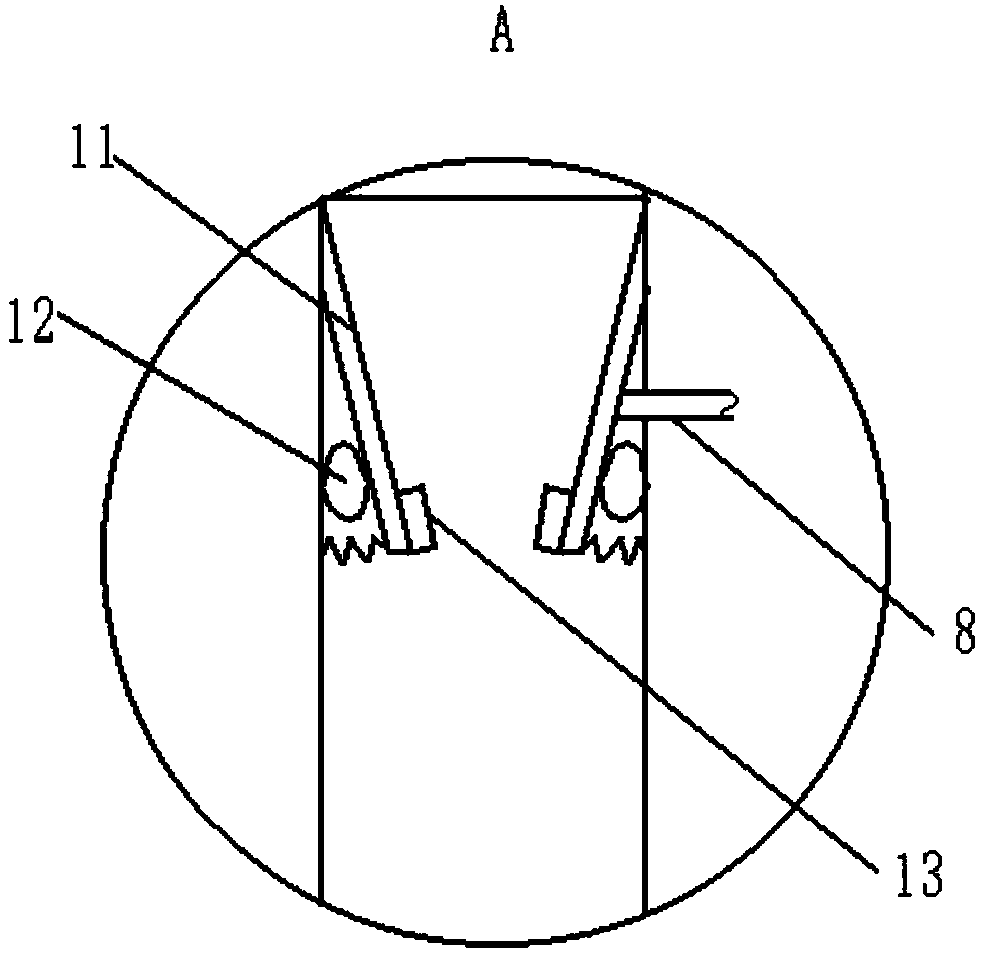
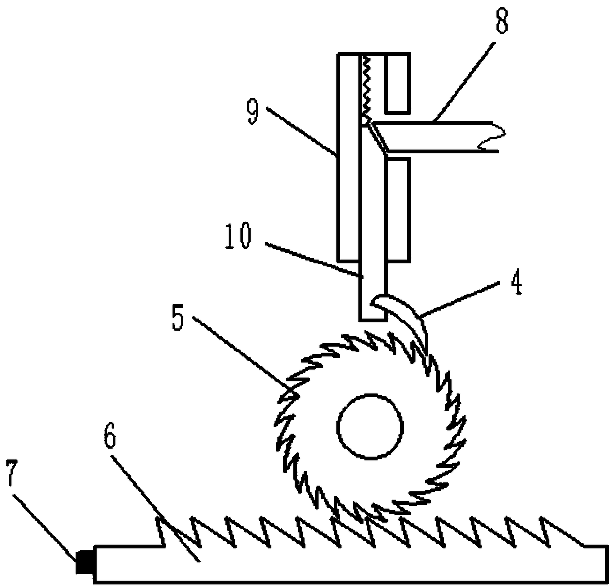
[0025] The reference signs in the drawings of the description include: housing 1, saw blade 2, disc 3, pawl 4, ratchet 5, rack 6, pressure block 7, push rod 8, guide rail 9, slide rod 10, pressure plate 11, Air bag 12, polishing block 13, normally closed switch 14, material placement platform 15, cylinder 16, processing platform 17, timber 18.

[0026] Such as figure 1 Shown: the tool failure prevention system of the machining center includes a machining table 17 and a circular saw. The machining table 17 is also provided with a material placement table 15, a cylinder 16, a normally closed switch 14 and a controller (not shown in the figure), and the cylinder The output shaft of 16 connects the material table 15, and the cylinder 16 can drive the material table 15 to move towards the circular saw direction, and the normally closed switch 14 circuits are connected to the controller. ...


PUM


Abstract

The invention relates to the technical field of mechanical failure prevention, in particular to a machining center tool failure preventing system which comprises a disk saw and further comprises a material storage table, a cylinder, a controller and a normally-closed switch. The disk saw comprises a shell, a disk and a plurality of saw webs. An output shaft of the cylinder is connected with the material storage table. The disk is connected with a power device. The normally-closed switch is connected with the controller through a circuit. The controller can control the cylinder and the power device. The saw webs are circumferentially and evenly distributed on the disk. A pressing plate is arranged in the shell. One end of the pressing plate is fixed to the shell, and the other end of the pressing plate is connected to the shell through a spring. A grinding block is arranged on the pressing plate. An air bag is connected between the pressing plate and the shell and provided with a through hole. A pushing rod is arranged on the pressing plate. The pushing rod horizontally extends out of the shell and is connected with a transmission mechanism. The transmission mechanism is connected with a pressing block capable of pressing the normally-closed switch. By means of the scheme, the problem that tool abrasion cannot be prevented in time during wood cutting is solved, and the dust removal aim is realized.

Description

technical field [0001] The invention relates to the technical field of mechanical failure prevention, in particular to a tool failure prevention system of a machining center. Background technique [0002] With the rapid development of social production and science and technology, mechanical products are becoming more and more sophisticated and frequently modified, especially for mechanical parts required in aerospace, shipbuilding, military and other fields, which require high precision, complex shapes, and small batches. Processing such products requires frequent modification or adjustment of equipment. Ordinary milling machines or highly specialized automatic milling machines can no longer meet these requirements. In order to solve the above problems, CNC milling machines have appeared on the market. CNC milling machines are divided into two categories without tool magazines and with tool magazines. Among them, CNC milling machines with tool magazines are called machining ...

Claims


Application Information

Patent Timeline
Patent Type & Authority Applications(China)
IPC IPC(8): B27B5/00B27B5/29B27G19/02B27G3/00
CPCB27B5/00B27B5/29B27G3/00B27G19/02
Inventor 孙兵涛周余庆高晨雷芝
Owner INST OF LASER & OPTOELECTRONICS INTELLIGENT MFG WENZHOU UNIV
Why Eureka
Try Eureka