
A combined endothermic and exothermic hydrogen production reactor

A hydrogen production reactor, heat absorption and exothermic technology, applied in the field of hydrogen energy, can solve the problems of low reaction temperature of endothermic reaction, decrease of reaction conversion rate, failure to proceed normally, etc., achieve scale optimization, easy control, and solve the problem of uneven material distribution uniform effect

Active Publication Date: 2019-11-29
江苏尚亿氢能源科技有限公司
View PDF3 Cites 2 Cited by
  • Summary
  • Abstract
  • Description
  • Claims
  • Application Information

AI Technical Summary

Problems solved by technology

For this kind of reactor where endothermic reaction and exothermic reaction are carried out simultaneously, when the amount and speed of endothermic and exothermic reactions are inconsistent, it will be directly manifested by the change of reaction temperature. The area of ​​endothermic reaction is characterized by high reaction temperature, which is more likely to cause severe local overheating, which will lead to early deactivation of the catalyst, increased side reactions, and unqualified product gas; while the heat release rate is too slow, it will lead to endothermic The reaction temperature of the reaction is too low, which directly leads to a decrease in the conversion rate of the reaction, or even fails to proceed normally.

Method used


Image

  • A combined endothermic and exothermic hydrogen production reactor
  • A combined endothermic and exothermic hydrogen production reactor
  • A combined endothermic and exothermic hydrogen production reactor

Examples


Embodiment

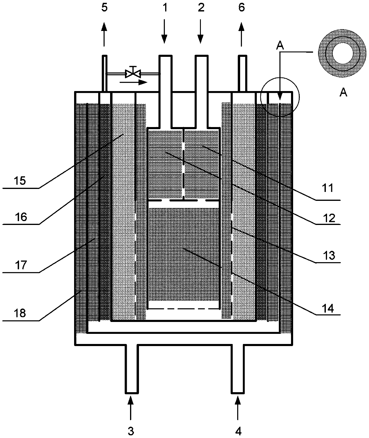
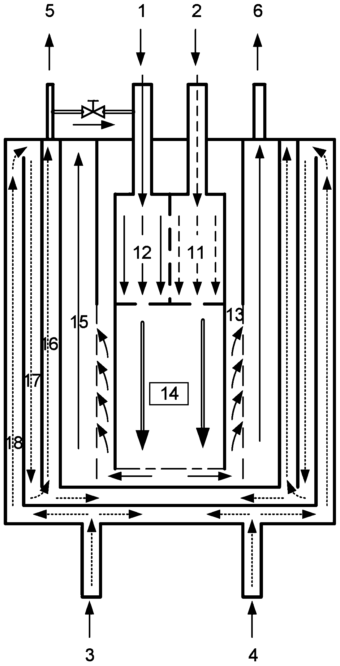
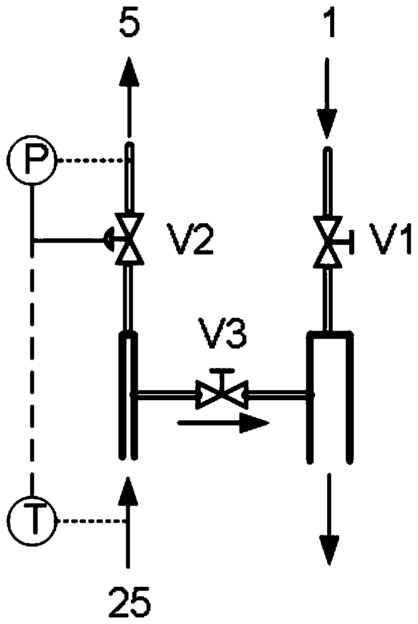
[0028] Such as figure 1 As shown, a schematic diagram of an axial cross-section of a hydrogen production reactor coupled with heat absorption and release, the reactor is a concentric multi-layer cylindrical structure, and from the outer layer to the inner layer are successively low-temperature reaction raw material chambers 18 and high-temperature reaction raw material chambers 17, the hydrogen production reaction chamber 16, the combustion reaction chamber 15, the combustion distribution chamber 13, the combustion mixing chamber 14 and the buffer chamber above the combustion mixing chamber 14. The hydrogen production reactor has 4 material inlets and 2 material outlets. The material inlets are: combustion raw material inlet 1, air inlet 2, hydrogen production raw material inlet 3 and water inlet 4; material outlets are: product gas outlet 5 and combustion tail gas exit6. An air inlet 2 is provided above the air buffer chamber 11, a combustion raw material inlet 1 is provided...


PUM

PropertyMeasurementUnit
diameteraaaaaaaaaa
diameteraaaaaaaaaa
diameteraaaaaaaaaa

Abstract

The invention relates to a heat absorption and heat release coupled hydrogen production reactor. The reactor is of a concentric circle type multilayered cylindrical structure and comprises a low-temperature reaction raw material cavity, a high-temperature reaction raw material cavity, a hydrogen production reaction cavity, a combustion reaction cavity, a combustion distribution cavity, a combustion mixing cavity and a buffering cavity in sequence from an outer layer to an inner layer. According to the reactor provided by the invention, high heat transferring efficiency of the reactor and uniform distribution of reaction temperature are ensured by sufficiently utilizing effective matching of an airflow distribution design and different reactions, and reasonable distribution of heat of a system and stable operation of the system are effectively realized. The buffering cavity, the distribution cavity, the mixing cavity and the distribution cavity of raw materials are designed, so that theproblem that the materials in a small-size reaction space are uniformly distributed is solved. A valve group is designed so that the energy efficiency of the hydrogen production reactor is improved.To sum up, the hydrogen production reactor provided by the invention has the appearance characteristics of compactness and small size, has the advantages of high combustion efficiency and heat transferring efficiency, and capability of reducing heat transferring resistance in a heat absorption process and a heat release process, and has a good application prospect.

Description

technical field [0001] The invention belongs to the technical field of hydrogen energy, and specifically relates to a hydrogen production reactor coupled with heat absorption and heat absorption, which converts hydrogen-containing raw materials (alcohols, alkanes, etc.) into hydrogen-rich gas through the matching of strong heat release and strong heat absorption. Background technique [0002] With the development of society, many problems such as energy shortage, environmental pollution and greenhouse effect have become the focus of attention of governments all over the world. In order to protect the environment on which human beings live and sustain economic development, the development of clean new energy and renewable energy is becoming a common choice for economic development of all countries in the world. As a zero-carbon or low-carbon energy, hydrogen energy can be stored and conveniently transported. The "hydrogen economy" centered on it may bring about major changes ...

Claims


Application Information

Patent Timeline
Patent Type & Authority Patents(China)
IPC IPC(8): C01B3/38C01B3/36C01B3/32
CPCC01B3/32C01B3/363C01B3/38C01B2203/0233C01B2203/0816C01B2203/1223C01B2203/1229C01B2203/1241
Inventor 潘立卫张晶钟和香周毅
Owner 江苏尚亿氢能源科技有限公司
Learn More