
Multi-channel parallel optical device spectral response measuring method and device

A spectral response and multi-channel technology, applied in the field of optical device measurement, can solve problems such as high signal-to-noise ratio, small measurement range, and large dynamic range, and achieve the effects of high resolution, improved measurement range, and large measurement range

Active Publication Date: 2018-09-21
NANJING UNIV OF AERONAUTICS & ASTRONAUTICS
View PDF5 Cites 5 Cited by
  • Summary
  • Abstract
  • Description
  • Claims
  • Application Information

AI Technical Summary

Problems solved by technology

However, this method still cannot meet the measurement range of several THz for optical devices
[0003] In order to further improve the measurement range, Xue Min et al. in "Wideband optical vector network analyzer based on optical single-sideband modulation and optical frequencycomb" (M.Xue, Y.J.Zhao, X.W.Gu and S.L.Pan, "Performance analysis of optical vector analyzer based on optical single-sideband modulation,"Journal of the Optical Society of America B,vol.30,no.4,pp.928-933,Apr.2013.) combined optical frequency comb with optical vector analysis technology based on optical single-sideband modulation Combined, the measurement range is greatly increased, but the disadvantages of this method are: 1. Each channel needs to be measured in turn. If the time to measure one channel is T, then the time to measure N channels is NT. The wider the measurement range The larger the measurement time is, the longer the measurement time is, which is contrary to the actual demand. In actual measurement, the measurement time is required to be as short as possible, so that the measurement efficiency can be improved; 2. Since the rejection ratio of the filter is limited in practice, the In the case that the other comb teeth are still left, these residual comb teeth will also generate modulation signals, which include not only single sideband signals, but also high-order sidebands, which will be compared with adjacent sidebands in the photodetector. The beating frequency of the belt or residual comb signal produces the same frequency component as the measurement result, and the crosstalk between different channels causes a huge measurement error; 3. There is wavelength dependence. Once the wavelength of the carrier wave changes, a follow-up measurement device center is required wavelength changes
Disadvantages of this method: 1. The number of measurement points is equal to the number of teeth of the optical frequency comb, so the resolution is very low, which is not suitable for measuring narrow-spectrum optical devices; 2. To ensure a certain resolution, the repetition frequency of the optical frequency comb should be small. The measurement range is small, and it is not suitable for measuring wide-spectrum optical devices; 3. In order to achieve the purpose of fast measurement, time-domain reception method (time-domain sampling instruments such as DSP or oscilloscope) must be used, but higher signal-to-noise ratio and large dynamic range
[0005] From the above analysis, it can be seen that it is very difficult to meet the requirements of large measurement range, high resolution and fast measurement at the same time

Method used


Image

  • Multi-channel parallel optical device spectral response measuring method and device
  • Multi-channel parallel optical device spectral response measuring method and device
  • Multi-channel parallel optical device spectral response measuring method and device

Examples


Embodiment Construction

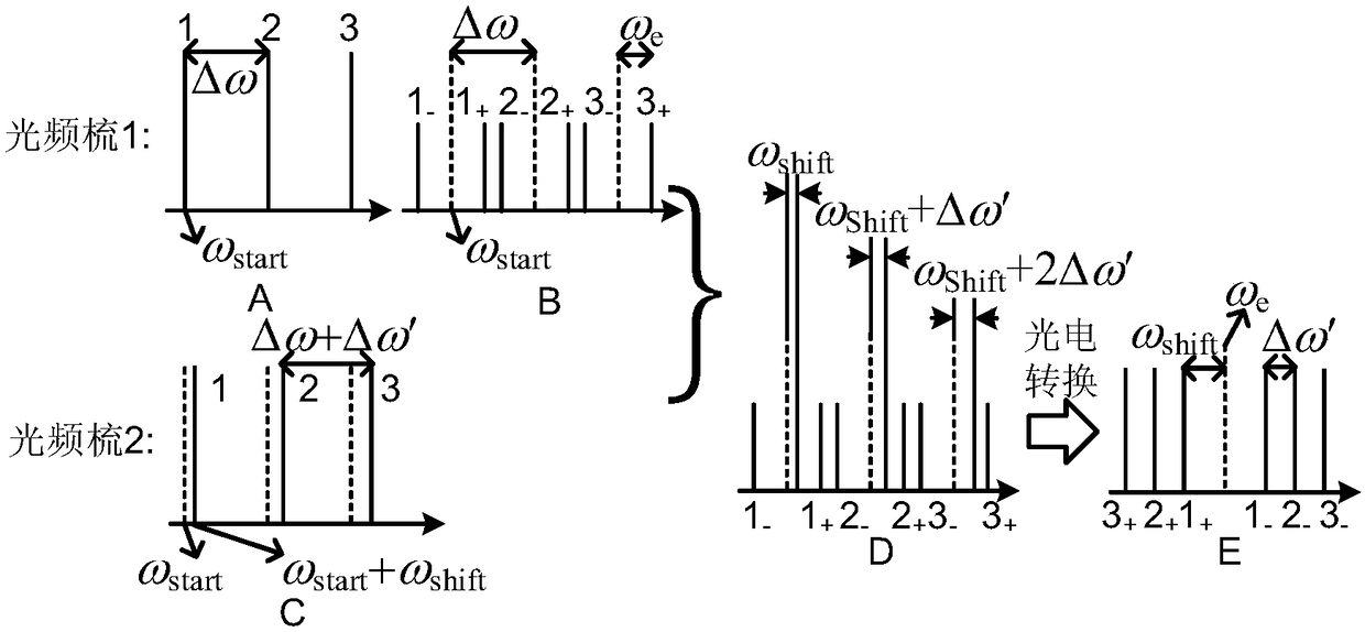
[0044] Aiming at the deficiencies of the existing technology, the idea of ​​the present invention is based on the existing optical device measurement method based on asymmetric double sideband modulation, using two sets of optical frequency comb signals with different frequency intervals of comb teeth to generate multi-channel asymmetric double sideband signal; because the frequency intervals of the comb teeth of the two groups of optical frequency comb signals are different, the frequency difference between the double sideband signals of different channels in the multi-channel asymmetric optical double sideband signal and the corresponding local oscillator signal is different, and the two are in the photodetector After the beat frequency is converted into an electrical signal, the frequency is different, which avoids the signal aliasing of different channels. In this way, the spectral response carried by the detection signal of multiple channels can be received in parallel, and...


PUM


Abstract

The invention discloses a multi-channel parallel optical device spectral response measuring method. The method comprises the following steps: step 1, modulating a microwave signal to a first optical frequency comb signal, and generating a multi-channel carrier suppression optical double-sideband signal; coupling the microwave signal with a second optical frequency comb signal, and generating a multichannel asymmetric optical double-sideband signal, that is a detection optical signal; and the comb frequency intervals of the first optical frequency comb signal and the second optical frequency comb signal are different; step 2, performing photoelectric conversion on the detection optical signal after passing through a to-be-measured optical device, and then extracting the spectral response ofthe to-be-measured optical device in each channel in parallel from the detection optical signal; and step 3, combining the spectral response of the to-be-measured optical device on each channel intothe complete spectral response of the to-be-measured optical device. The invention further discloses a multi-channel parallel optical device spectral response measuring device. According to the multi-channel parallel optical device spectral response measuring method provided by the invention, high-resolution and wide-range fast high-precision measurement can be realized at the same time, mutual crosstalk of different channels is avoided, and the frequency dependence of a receiver and measurement errors caused by nonlinear modulation are effectively eliminated.

Description

technical field [0001] The invention relates to a method for measuring the spectral response of an optical device, in particular to a method and device for measuring the spectral response of an optical device in parallel with multiple channels, and belongs to the technical field of optical device measurement. Background technique [0002] In recent years, with the rapid development and popularization of optical communication, photon technology has been rapidly developed and continuously improved, and the requirements for optical device measurement technology, which are indispensable in the process of optical device manufacturing, production, application, and testing, are also increasing. Higher and higher. However, the existing optical device measurement technology has many problems such as low measurement accuracy and resolution, and small measurement range. In 1998, J.E.Roman proposed an optical vector analysis method based on optical single sideband modulation [J.E.Román...

Claims


Application Information

Patent Timeline
Patent Type & Authority Applications(China)
IPC IPC(8): H04B10/077G01M11/00
CPCG01M11/00H04B10/077H04B10/0775
Inventor 潘时龙卿婷李树鹏薛敏
Owner NANJING UNIV OF AERONAUTICS & ASTRONAUTICS
Learn More