Indoor visible light visual positioning method and hardware system thereof

A visual positioning and visible light technology, which is applied in the field of visible light communication, can solve problems affecting positioning stability and poor accuracy of bright and dark stripes, and achieve the effects of eliminating low accuracy, increasing distance, and reducing burden

Pending Publication Date: 2018-09-25
SOUTH CHINA UNIV OF TECH
View PDF11 Cites 19 Cited by
  • Summary
  • Abstract
  • Description
  • Claims
  • Application Information

AI Technical Summary

Problems solved by technology

[0005] The purpose of the present invention is to overcome the shortcomings and deficiencies in the prior art, and provide an indoor visible light positioning method, which can effectively overcome the influence

Method used


Image

  • Indoor visible light visual positioning method and hardware system thereof
  • Indoor visible light visual positioning method and hardware system thereof
  • Indoor visible light visual positioning method and hardware system thereof

Examples


Embodiment

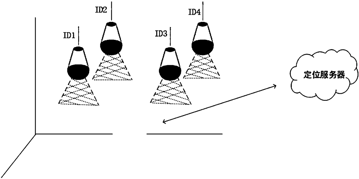
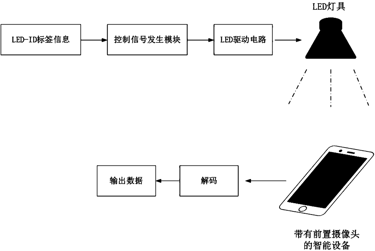
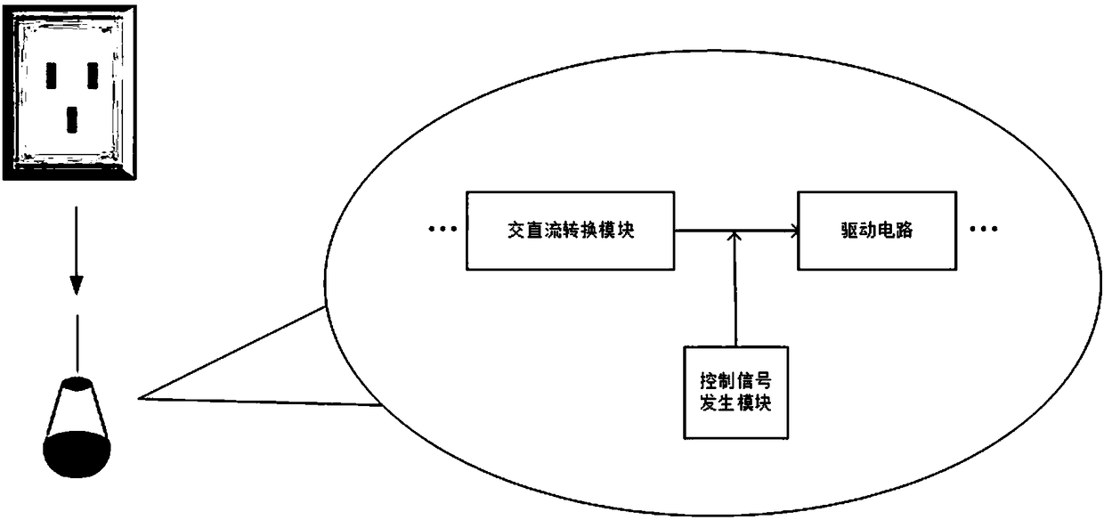
[0046] like figure 1 and figure 2 As shown, the present invention is based on the visual visible light positioning technology. At the transmitting end, the ID number (LED-ID) label information of the LED lamp is passed through the control signal generation module to complete the encoding process, and a series of control signals are generated and transmitted to the LED drive circuit, thereby controlling the LED The light turns on and off, and the encoded information is sent to the optical channel space. The receiving end of the mobile device uses a CMOS sensor to obtain light signals to form images of different light and dark stripe widths, and obtains the coordinates of the lamps after processing to complete the image decoding process. Finally, the positioning is realized by the camera-based Angle of Acceptance (AOA) positioning optimization algorithm.

[0047] In a specific embodiment, the implementation and working process of the indoor visible light vision positioning me...


PUM


Abstract

The invention discloses an indoor visible light visual positioning method and a hardware system thereof. The method comprises the following steps: allowing a transmitting end LED lamp to emit a modulated optical signal; allowing a receiving end of a mobile device to use a CMOS image sensor to acquire the optical signal to form images having different light and dark stripe widths; using the multi-iteration average manner to eliminate background light disturbance of the images received by the image sensor; acquiring an image frequency domain signal by using fast Fourier transform (FFT), and filtering the image frequency domain signal; selecting a peak frequency from the processed image frequency domain signal as a frequency value corresponding to the lamp ID; comparing the peak frequency with a frequency-coordinate database in a positioning server to acquire coordinates of the lamp, and completing an image decoding process; and finally realizing positioning of the receiving end of the mobile device through the reception angle (AOA) positioning algorithm. The method can increase the distance of demodulating the visible light signal, improve the information detection performance of thereceiving end of the mobile device, and further improve the precision of the visible light positioning system.

Description

technical field [0001] The invention relates to visible light communication technology, in particular to an indoor visible light vision positioning method and a hardware system thereof. Background technique [0002] Visible light communication is a technology that can build a wireless communication network by adding data transmission functions to basic public lighting facilities. Compared with traditional wireless communication technologies, visible light communication technology has the advantages of rich bandwidth resources and no electromagnetic interference. Due to the influence of multipath effect and path loss, traditional GPS navigation and positioning cannot meet people's requirements for positioning accuracy. Other indoor positioning systems based on Bluetooth, WIFI, ultrasound, and infrared have not been widely used due to positioning accuracy and installation costs. [0003] Visible light positioning is a technology to improve the accuracy of indoor positioning. ...

Claims


Application Information

Patent Timeline
IPC IPC(8): G01S5/16H04B10/116H04B10/50H04B10/524
CPCH04B10/116H04B10/502H04B10/524G01S5/16
Inventor 吴玉香刘晓伟关伟鹏
Owner SOUTH CHINA UNIV OF TECH
Why Eureka
Try Eureka