High-efficiency F type stacking power amplifier based on right and left hand transmission lines

A power amplifier, power amplification technology, applied in amplifiers, amplifiers with semiconductor devices/discharge tubes, amplifier input/output impedance improvement and other directions, can solve the problem that the harmonic impedance control unit occupies a large circuit size, power output capability and Problems such as low power gain capability, indicators affecting circuit miniaturization, etc., achieve the effect of simplifying the peripheral gate power supply structure, improving power capacity and power gain, and reducing circuit size

Pending Publication Date: 2018-09-25
CHENGDU GANIDE TECH
View PDF16 Cites 5 Cited by
  • Summary
  • Abstract
  • Description
  • Claims
  • Application Information

AI Technical Summary

Problems solved by technology

However, in the design of traditional high-efficiency power amplifiers, there have always been some design problems, mainly reflected in the mutual constraints of miniaturization and high-efficiency indicators: in order to ensure the high-efficiency operation of the amplifier, the transistor must work in the overdrive mode, similar to the switch state, but the harmonic impedance control unit of the overdrive switching power amplifier often needs to occupy a larger circuit size, which affects the miniaturization index of the circuit
[0003] There are many circuit structures of common high-efficiency power amplifiers, the most typical ones are traditional class AB, class C, switching type power amplifiers of class D, class E, and class F, etc. However, these high-efficiency amplifiers still have some shortcomings, mainly reflected in In: The theoretical limit efficiency of the traditional class AB amplifier is 78.5%, which is relatively low; the limit efficiency of the class C amplifier is 100%, but the power output capability is low; switching type D, E, F power amplifiers, etc. need to rely on accurate Harmonic impedance control, or strict impedance matching conditions, these controls and conditions often need to occupy a large circuit size
In addition, the existing high-efficiency FET power amplifiers are often implemented based on a single common-source transistor, which is limited by a single transistor, and the power output capability and power gain capability are relatively low

Method used


Image

  • High-efficiency F type stacking power amplifier based on right and left hand transmission lines
  • High-efficiency F type stacking power amplifier based on right and left hand transmission lines

Examples


Embodiment Construction

[0023] Exemplary embodiments of the present invention will now be described in detail with reference to the accompanying drawings. It should be understood that the implementations shown and described in the drawings are only exemplary, intended to explain the principle and spirit of the present invention, rather than limit the scope of the present invention.

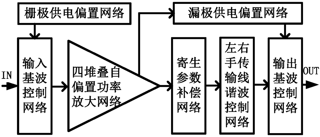
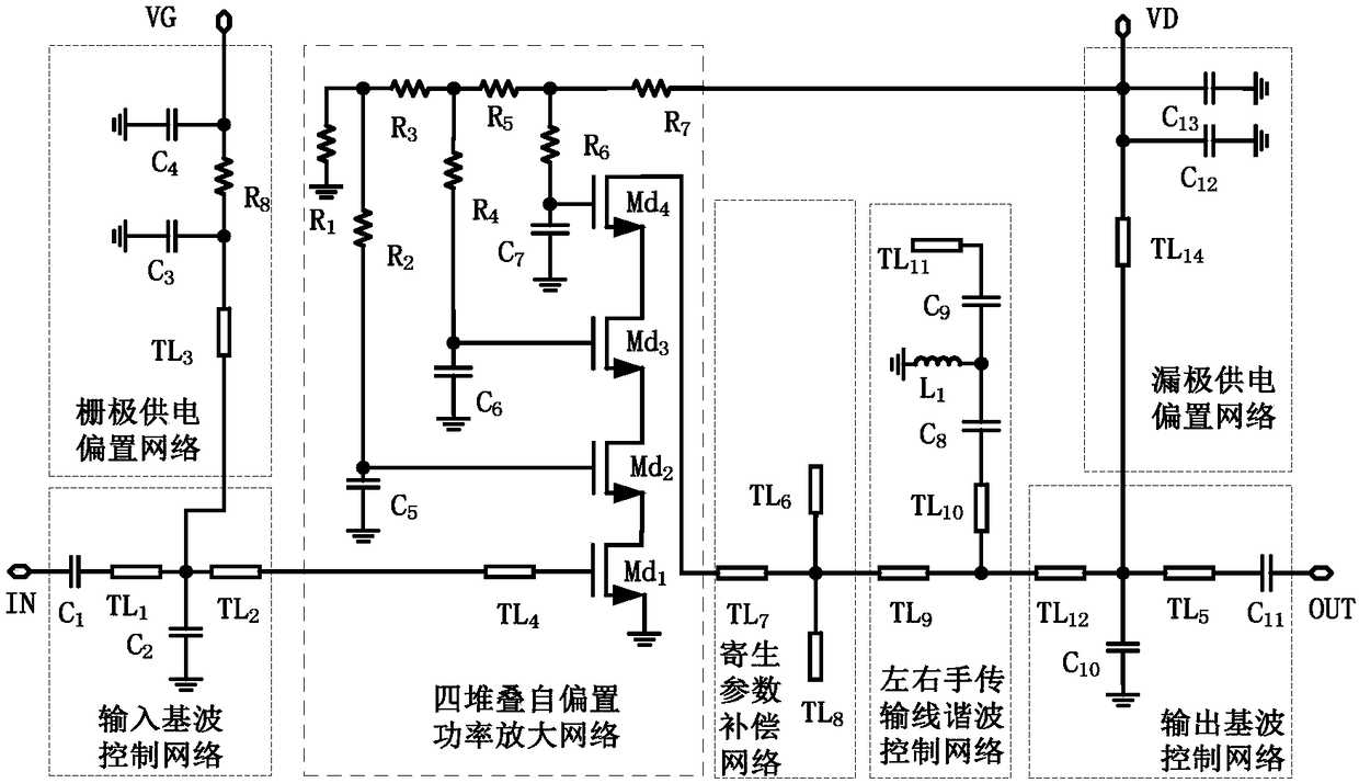
[0024] An embodiment of the present invention provides a high-efficiency Class F stacked power amplifier based on left and right handed transmission lines, such as figure 1 As shown, including the input fundamental control network, quad-stack self-biased power amplifier network, parasitic parameter compensation network, left and right handed transmission line harmonic control network, output fundamental control network, gate supply bias network, and drain supply bias network ; The input fundamental wave control network, the four stacked self-biased power amplification network, the parasitic parameter compensation network...


PUM


Abstract

The invention discloses a high-efficiency F type stacking power amplifier based on right and left hand transmission lines. The high-efficiency F type stacking power amplifier comprises an input fundamental wave control network, a four-stacking self-bias power amplification network, a parasitic parameter compensation network, a right and left hand transmission line harmonic control network, an output fundamental wave control network, a gate power supply bias network, and a drain power supply bias network. The high-efficiency F type stacking power amplifier disclosed by the invention adopts a four-stacking transistor structure based on a self-bias structure, and combines a high-efficiency F type matching mode of the right and left hand transmission line harmonic control network, so that thecircuit can independently control the fundamental wave, second harmonic impedance and third harmonic impedance of the output impedance while having the transistor parasitic compensation capability, high-efficiency, high-grain and high-power output capability of the amplifier is achieved, and a relatively small circuit size is occupied.

Description

technical field [0001] The invention belongs to the technical field of field effect transistor radio frequency power amplifiers and integrated circuits, and in particular relates to the design of a high-efficiency class F stack power amplifier based on left and right hand transmission lines. Background technique [0002] With the development of modern military and civilian communication technologies, RF front-end transmitters are also developing in the direction of miniaturization, high efficiency, high gain, and high power output. Therefore, the market urgently needs miniaturized, high-efficiency, high-gain, and high-power power amplifiers. However, in the design of traditional high-efficiency power amplifiers, there have always been some design problems, mainly reflected in the mutual constraints of miniaturization and high-efficiency indicators: in order to ensure the high-efficiency operation of the amplifier, the transistor must work in the overdrive mode, similar to th...

Claims


Application Information

Patent Timeline
Patent Type & Authority Applications(China)
IPC IPC(8): H03F3/217H03F1/56
CPCH03F1/565H03F3/217
Inventor 滑育楠邬海峰陈依军胡柳林吕继平王测天童伟
Owner CHENGDU GANIDE TECH
Why Eureka
Try Eureka