Three-dimensional detecting device and method for wear of cutting edge of side edge of milling cutter

A three-dimensional detection and cutting edge technology, used in measuring/indicating equipment, metal processing mechanical parts, metal processing equipment, etc., can solve problems such as affecting detection accuracy, and achieve the goal of ensuring product quality, improving processing accuracy and efficiency, and avoiding losses. Effect

Active Publication Date: 2018-09-28
HARBIN UNIV OF SCI & TECH
View PDF8 Cites 12 Cited by
  • Summary
  • Abstract
  • Description
  • Claims
  • Application Information

AI Technical Summary

Problems solved by technology

[0003] The traditional tool wear detection method is generally based on the cutting force, vibration and sound signals in the process of processing to detect wear. By analyzing the relationship between these signals and the amount of tool wear to determine the degree of tool wear, it can be seen that this method has a lot of problems. Randomness, if the analysis of the relationship between the signal and the tool wear is inaccurate, it will seriously affect the detection accuracy
Detecting tool wear based on machine vision technology can detect the intuitive wear state of the tool. In most cases, the VB value calculated from the two-dimensional image of tool wear is used to judge the degree of tool wear, ignoring the wear volume of the tool edge. The machining accuracy is affected, so a three-dimensional detection technology is needed to determine the wear degree of the cutting edge of the tool, and judge whether it is necessary to change a new knife for the processing of the following process, so as to ensure the machining accuracy and efficiency, and avoid the scrapped parts due to tool wear. Phenomenon, improve the economic benefits in the process of processing

Method used


Image

  • Three-dimensional detecting device and method for wear of cutting edge of side edge of milling cutter
  • Three-dimensional detecting device and method for wear of cutting edge of side edge of milling cutter
  • Three-dimensional detecting device and method for wear of cutting edge of side edge of milling cutter

Examples


Embodiment Construction

[0024] The technical solution of the present invention will be further specifically described below through the embodiments in conjunction with the accompanying drawings. Obviously, the described embodiments are only a part of the embodiments of the present invention, rather than all embodiments. It should be understood that the present invention described herein The specific examples are only used to explain the present invention, not to limit the present invention.

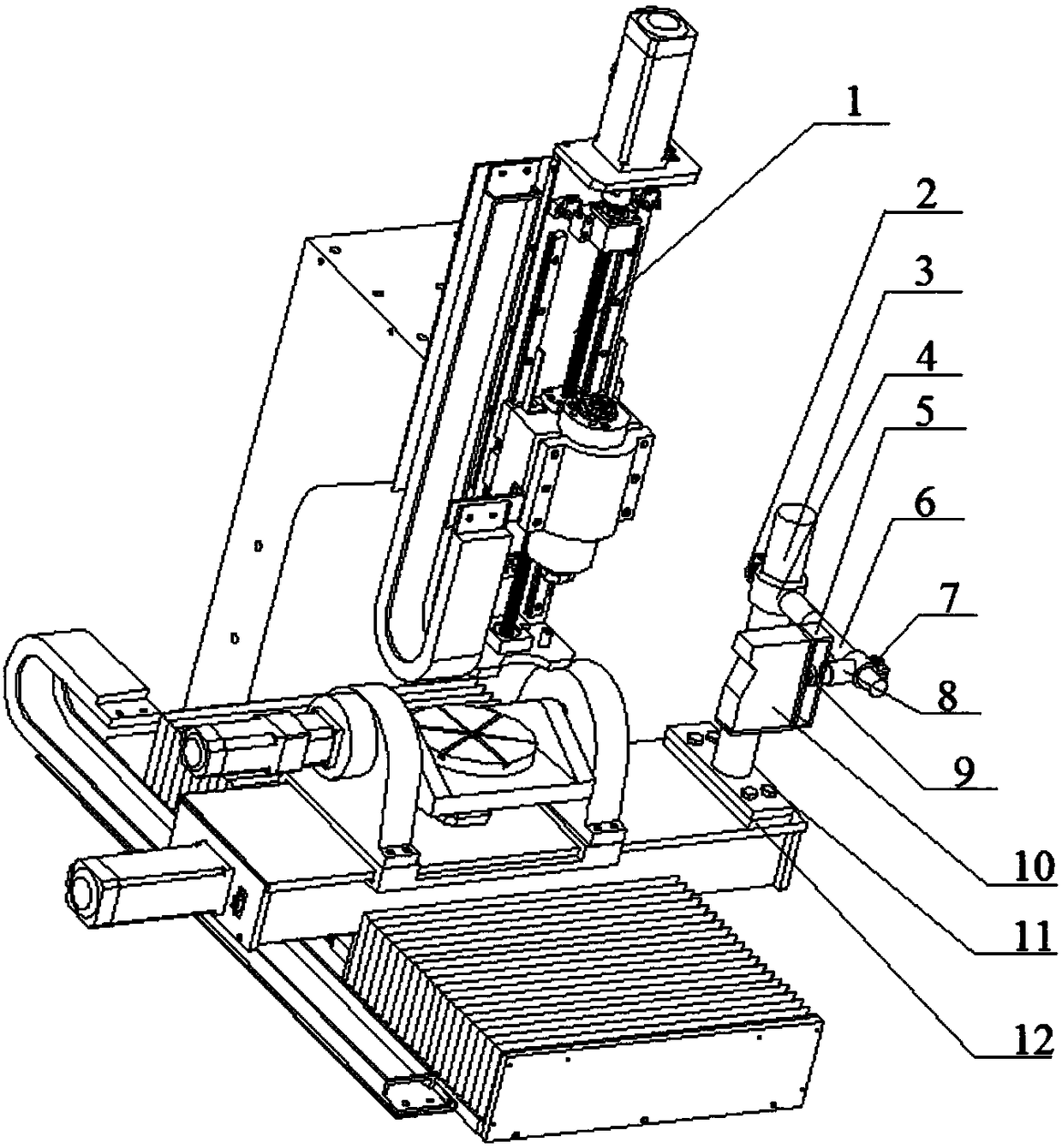
[0025] Such as Figure 1-Figure 6 , a three-dimensional detection device and method for milling cutter side edge wear, using a camera adjustment device to install a three-dimensional camera on a CNC machine tool, the three-dimensional camera can collect tool edge contour data, and use the MFC development platform of Visual C++6.0 A tool wear detection system is established, which is composed of industrial computer-machine tool communication, image acquisition, data processing and wear amount calculation modules....


PUM


Abstract

The invention provides a three-dimensional detecting device and method for wear of a cutting edge of a side edge of a milling cutter. A cutter wear detecting system is set up through a Visual C++6.0 MFC development platform, the outline data of the cutting edge of the cutter are collected through a three-dimensional detecting camera, data processing is carried out in the system, and the wear amount is worked out. The method comprises the following steps that firstly, the camera is fixed, and the relative positions of the camera and the cutter are adjusted; secondly, camera calibration and camera exposure value adjustment are carried out in the detecting system; thirdly, the outline data of the cutting edge of the cutter are collected through the camera according to a set collection path and are transmitted to a computer; and fourthly, the detecting system carries out denoising and smoothing processing on the data, and the wear amount is worked out. The three-dimensional detecting device and method for wear of the cutting edge of the side edge of the milling cutter have the advantages of being high in detecting precision, simple in structure and reliable in work and have high practicality in actual machining.

Description

Technical field: [0001] The invention relates to a tool edge wear detection device and method, in particular to a milling cutter side edge wear three-dimensional detection device and method. Background technique: [0002] With the rapid development of aerospace technology, higher requirements are put forward for the machining accuracy of its parts. Titanium alloy thin-walled parts are widely used in the aerospace industry. Due to the material properties and structural characteristics of parts, titanium alloy materials are processed It is not easy to conduct heat, and it is easy to cause accelerated tool wear, which makes it difficult to guarantee the machining accuracy of thin-walled parts. Tool wear is ubiquitous in the machining process. With the increase of machining time, the degree of tool wear continues to increase. Tools with different degrees of wear have an important impact on the machining accuracy, efficiency and economic benefits of parts during the machining pro...

Claims


Application Information

Patent Timeline
Patent Type & Authority Applications(China)
IPC IPC(8): B23Q17/09B23Q17/24
CPCB23Q17/0957B23Q17/2452
Inventor 刘献礼夏伟孟博洋李宏宇
Owner HARBIN UNIV OF SCI & TECH
Why Eureka
Try Eureka