Energy-conservation and noise-reduction circular conveying device

A transmission device and noise reduction technology, applied in conveyor control devices, transportation and packaging, conveyors, etc., can solve problems such as increasing the power consumption of driving mechanisms, affecting the working environment, and affecting the quality of processed products, etc. Avoid deviation and/or sway, ensure smooth running, reduce the effect of contact area

Active Publication Date: 2018-09-28
苏州优王电子科技有限公司
View PDF27 Cites 19 Cited by
  • Summary
  • Abstract
  • Description
  • Claims
  • Application Information

AI Technical Summary

Problems solved by technology

But this CN107117439A still has the following shortcomings: one, due to the need to set the front, rear and left and right ends of the upper part of the guide platform in the flow tank (i.e. "station flow tank", hereinafter the same) in an interval state for a group of station division parts to carry The structural system of the mechanism is that the lower workpiece container guides the supporting roller, and the bottom of the lower workpiece container contacts the roller. Under the traction of the double-row transmission chain (that is, the transmission chain, the same below), the lower workpiece container and the upper workpiece container flow around The guide platform of the water tank moves around in an elliptical motion track (see paragraph 0043 of the patent specification for details), and the movement mode of a group of station division parts bearing mechanism is negative movement. During the movement, The bottom of the lower workpiece container, that is, the friction between the bottom surface and the roller will make a lot of noise. At the same time, after a long period of friction between the lower workpiece container and the roller, the galvanized layer on the surface of the roller will be worn away, causing rust and affecting the service life. In addition, the rust will also be dirty and the processed products, which will affect both the working environment and the quality of the processed products, and because the total contact area between the lower workpiece container and the roller is large, resulting in a large relative friction area and increasing the power of the driving mechanism Consumption is unfavorable for saving electric energy consumption; Its two, because the lower workpiece container of the structural system of a group of station division parts carrying mechanism is by being fixed on the lower workpiece container towards the lower workpiece container of the double-row transmission chain side of the structural system of the drive mechanism The hanging legs are connected to the traction piece of the workpiece container on the double-row transmission chain, so the position of the lower workpiece container is relatively low. Specifically, the upper edge of the lower workpiece container is basically at the same level as the upper surface of the double-row transmission chain. Level (that is, in the same plane), so taking the processing of clothing as an example, once the garment pieces placed in the lower workpiece container cross or protrude out of the upper edge of the lower workpiece container, it is very easy to contact the double-row transmission chain, and there is Damage to the garment pieces, entangle the danger of the double-row transmission chain; third, because one end of the double-row transmission chain of the structural system of the drive mechanism is sleeved on the active double-row sprocket at an end of the guide platform that is positioned at the flow tank, and The other end of the double-row transmission chain is sleeved on the driven double-row sprocket located at the other end of the guide platform of the flow tank (see paragraph 0035 of the manual), and the middle part of the double-row transmission chain is in a free state without a bundle, so the double-row The transmission chain will deviate during operation, which will affect the stability of the movement of a group of station division component bearing mechanisms, and in severe cases will damage the upper station container and the lower station container of the station division component bearing mechanism. and many more

Method used


Image

  • Energy-conservation and noise-reduction circular conveying device
  • Energy-conservation and noise-reduction circular conveying device
  • Energy-conservation and noise-reduction circular conveying device

Examples


Embodiment Construction

[0026] In order to understand the technical essence and beneficial effects of the present invention more clearly, the applicant will describe in detail the following examples, but the descriptions of the examples are not intended to limit the solutions of the present invention. Equivalent transformations that are only formal but not substantive should be regarded as the scope of the technical solution of the present invention.

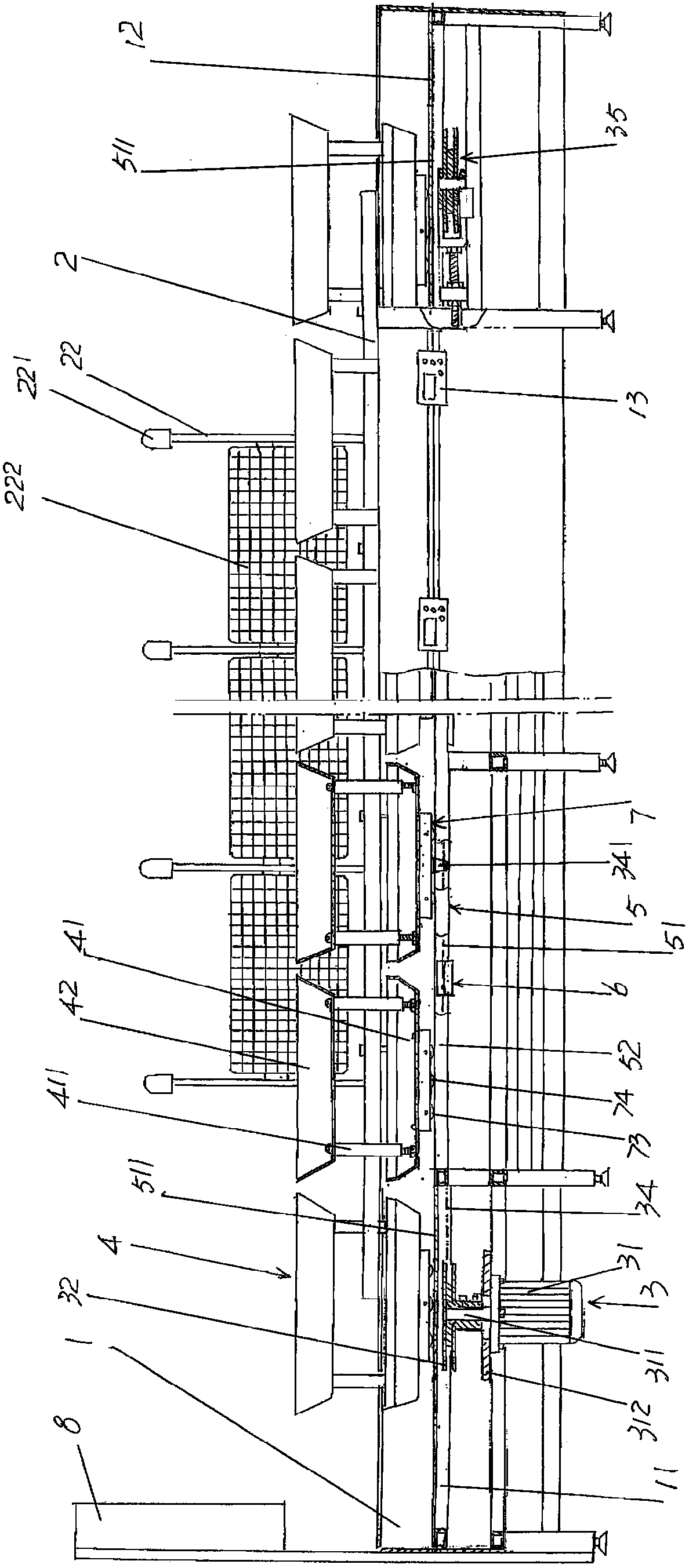
[0027] In the following descriptions, all concepts related to directionality or orientation of up, down, left, right, front and rear are based on figure 1 The location status is taken as an example, so it cannot be understood as a special limitation on the technical solution provided by the present invention.

[0028] See figure 1 , shows a station flow tank 1, the station flow tank is supported on the upper part of the station flow tank frame 11 and a guide platform 12 is formed on the top of the station flow tank 1, in the middle of the guide platfo...


PUM


Abstract

The invention discloses an energy-conservation and noise-reduction circular conveying device. The device comprises a station flowing tank, a center frame and a driving mechanism, wherein a guide platform is arranged at the upper part of the station flowing tank; a center frame cavity is formed in the middle part of the guide platform; the center frame is fixed with a station flowing tank frame; and the driving mechanism is arranged on the station flowing tank frame, and comprises a transmission chain and a set of station work division part bearing mechanisms. The device further comprises a roller guide mechanism, transmission chain guide mechanisms and a traction car; the roller guide mechanism is positioned in the center frame cavity, and is fixed on the station flowing tank frame; the transmission chain guide mechanisms are arranged on the roller guide mechanism at intervals; the traction car is connected with a transmission chain; the set of station work division part bearing mechanisms are connected with the traction car; and the transmission chain slidingly cooperates with the transmission chain guide mechanism. The contacted area of the guide platform with the roller guide mechanism is prominently reduced; the noise is prominently lowered; the energy conservation is achieved; workpieces and driving mechanisms are protected; the operation stability of the transmission chain is guaranteed; the structure is simplified; and the production cost is reduced.

Description

technical field [0001] The invention belongs to the technical field of assembly line production equipment for light industrial products, and in particular relates to an energy-saving and noise-reducing circular transmission device. Background technique [0002] The light industrial products mentioned above mainly refer to clothing, but are not limited to clothing, such as shoes, hats, bags, etc., electrical and electronic products, dolls and toys, etc. [0003] Taking a large-scale garment factory as an example, the production process of a piece of clothing includes cutting, sewing, opening buttonholes, buttoning (referred to as buttoning), bagging, collaring, sleeves, placket and There are several processes such as ironing, which are often carried out in a division of labor and automation. [0004] The cyclic transmission device and the matching intelligent control device have the following advantages: it can link up the employees who are originally scattered, cooperate wi...

Claims


Application Information

Patent Timeline
Patent Type & Authority Applications(China)
IPC IPC(8): B65G17/38B65G21/22B65G23/44B65G43/02
CPCB65G17/38B65G21/22B65G23/44B65G43/02
Inventor 尹术超
Owner 苏州优王电子科技有限公司
Why Eureka
Try Eureka