Hydraulic turbine device

A hydraulic turbine and turbine technology, which is used in electromechanical devices, safety devices, hydroelectric power generation, etc., can solve the problem of difficulty in adapting to high water head and changing working conditions, complex structure of multi-stage centrifugal turbines, and high manufacturing and maintenance costs. problem, to achieve the effect of simple structure, high reliability and high security

Inactive Publication Date: 2018-09-28
JIANGSU UNIV
View PDF13 Cites 5 Cited by
  • Summary
  • Abstract
  • Description
  • Claims
  • Application Information

AI Technical Summary

Problems solved by technology

Centrifugal turbines commonly used at present are difficult to adapt to high water head and variable working conditions, while multi-stage centrifugal turbines have complex structures, high manufacturing and maintenance costs, and low hydraulic efficiency

Method used


Image

  • Hydraulic turbine device
  • Hydraulic turbine device
  • Hydraulic turbine device

Examples


Embodiment Construction

[0036] The present invention will be further described below in conjunction with the accompanying drawings and specific embodiments.

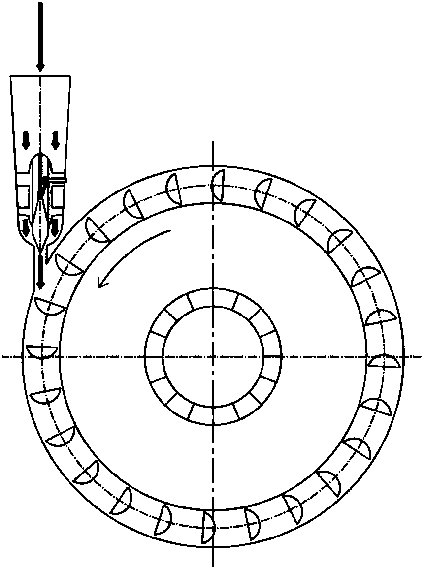
[0037] figure 1 It is a working schematic diagram of the hydraulic turbine device. The direction of water flow is shown in the direction of the arrow in the figure, and the direction of rotation of the runner is counterclockwise. The speed of the water flow at the entrance is low, and the speed increases after passing through the needle. When it flows through the throat of the volute, the kinetic energy is used to push the runner to drive the magnetic coupling to rotate and do work to generate electric energy.

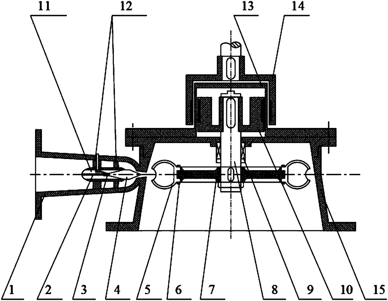
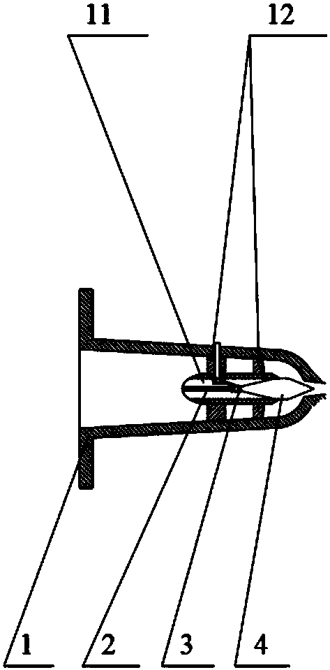
[0038] figure 2 It shows an assembly diagram of a hydraulic turbine described in this embodiment, including inlet device 1, guide rail 2, connecting rod 3, spray needle 4, runner blade 5, adjustment pin 6, runner hub 7, and main shaft 8 , Mechanical seal 9, inner magnet 10, bulb body 11, guide vane 12, isolation cover 13, outer magn...


PUM


Abstract

The invention belongs to the technical field of energy conversion, and particularly discloses a hydraulic turbine device. The turbine comprises an inlet device, a guide rail, a connecting rod, a spraypin, rotating wheel blades, an adjusting pin, a rotating wheel hub, a main shaft, a mechanical seal, an inner magnet, a bulb body, guide vanes, an isolation cover, an outer magnet and a volute, wherein the bulb body is arranged in the inlet device, and the spray pin controlled by the connecting rod to move is arranged in the inlet device, so that the flow control is realized; the rotating wheel blades and the rotating wheel hub are connected through the adjusting pin in a chained mode, and the angle of the rotating wheel blades is adjusted through the adjusting pin; and permanent magnetic blocks arranged at intervals are installed on the outer cylindrical surface of the inner magnet, the permanent magnets with opposite magnetic poles are correspondingly installed at the position which arecorresponding to the inner magnets and the inner surface of the outer magnet; and the isolation cover is placed between the inner magnet and the outer magnet, the inner material of the isolation cover is made of metal, and the outer surface of the isolation cover is provided with a plastic separation layer. The turbine device can adapt to working conditions of extremely high water heads, and is suitable for being installed on the downstream of a river channel so as to fully utilize the kinetic energy of the water flow, so that the kinetic energy can be efficiently converted into electric energy.

Description

technical field [0001] The invention belongs to the technical field of energy conversion, in particular to a hydraulic turbine device. Background technique [0002] A turbine is a machine that converts the energy contained in a fluid working medium into mechanical energy. There are a large number of high-pressure liquids in petrochemical, petroleum processing, chemical fertilizer, seawater desalination, iron and steel metallurgy and other industries, and the energy of these high-pressure liquids is mostly wasted at present. In foreign countries, some developed countries currently use the energy of these high-pressure liquids with special hydraulic energy recovery turbines, but in my country and some developing countries, most of the energy is wasted, and it has also been used in the fertilizer industry in China in recent years. A device that reverses the pump to recover, but due to the lack of design theory, the energy recovery efficiency is generally low, which leads to the...

Claims


Application Information

Patent Timeline
Patent Type & Authority Applications(China)
IPC IPC(8): F03B13/00F03B1/04F03B1/02F03B15/04F03B15/00F03B11/02H02K49/10
CPCF03B1/02F03B1/04F03B11/02F03B13/00F03B15/00F03B15/04F05B2220/706F05B2240/30F05B2270/328H02K49/104Y02E10/20
Inventor 付强陈铭朱荣生王秀礼刘刚李梦圆张国玉
Owner JIANGSU UNIV
Why Eureka
Try Eureka