Novel robot hydraulic joint drive system

A driving system and robot technology, applied in the direction of fluid pressure actuation system components, fluid pressure actuation devices, manipulators, etc., can solve problems such as large energy loss, achieve the effect of low motor power, stable pressure, and avoid large current discharge

Pending Publication Date: 2018-09-28
SOUTHWEST JIAOTONG UNIV
View PDF0 Cites 10 Cited by
  • Summary
  • Abstract
  • Description
  • Claims
  • Application Information

AI Technical Summary

Problems solved by technology

[0006] The purpose of the present invention is to provide a new type of robot hydraulic joint drive system, which solves the problem of large energy loss in the existing hydraulic drive system, and at the same time satisfies the corresponding response speed

Method used


Image

  • Novel robot hydraulic joint drive system

Examples


Embodiment 1

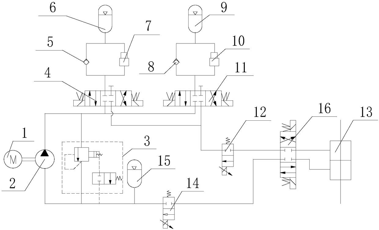
[0044] Such as figure 1 As shown, a novel robot hydraulic joint drive system includes a motor 1, a hydraulic pump 2 and a double-acting piston rod cylinder 13, the motor 1 is connected to the hydraulic pump 2, and the connection between the hydraulic pump 2 and the double-acting piston rod cylinder 13 An oil inlet circuit and an oil return circuit are formed in parallel between them, and the first high-pressure energy storage mechanism, the second high-pressure energy storage mechanism and the first proportional valve 12 are sequentially arranged on the oil inlet path from the hydraulic pump 2 to the double-acting piston rod cylinder 13 Or the first servo valve, the first high-pressure accumulator mechanism includes the first one-way valve 5 and the first high-pressure accumulator 6 forming a first circuit, and the first circuit is commutated through the first three-position four-way electromagnetic The valve 4 communicates with the oil inlet, and the second high-pressure accu...

Embodiment 2

[0046] Such as figure 1 As shown, this embodiment is based on Embodiment 1, and the first circuit also includes a first supercharger 7, the first supercharger 7 is arranged at the rear end of the first high-pressure accumulator 6, and the second circuit A second supercharger 10 is also included, and the second supercharger 10 is arranged at the rear end of the second high-pressure accumulator 9 .

Embodiment 3

[0048] Such as figure 1 As shown, this embodiment is based on Embodiment 1 or Embodiment 2, and the second proportional valve 14 or the second servo valve is arranged on the oil return line.


PUM


Abstract

The invention discloses a novel robot hydraulic joint drive system. The novel robot hydraulic joint drive system comprises a motor, a hydraulic pump and a double-action piston rod cylinder. The motoris connected with the hydraulic pump. An oil inlet way and an oil return way are formed between the hydraulic pump and the double-action piston rod cylinder in parallel. The part, from the hydraulic pump to the double-action piston rod cylinder, on the oil inlet way is sequentially provided with a first high-pressure energy storage mechanism, a second high-pressure energy storage mechanism and a first proportional valve or a first servo valve. The first high-pressure energy storage mechanism comprises a first one-way valve and a first high-pressure energy accumulator forming a first loop. Thefirst loop communicates with the oil inlet way through a first three-position four-way electromagnetic reversing valve. The second high-pressure energy storage mechanism comprises a second one-way valve and a second high-pressure energy accumulator forming a second loop. The second oil way communicates with the oil inlet way through a second three-position four-way electromagnetic reversing valve.The novel robot hydraulic joint drive system solves the problem that an existing hydraulic drive system is large in energy loss.

Description

technical field [0001] The invention relates to the technical field of robot drive systems, in particular to a novel robot hydraulic joint drive system. Background technique [0002] The driving system of industrial robots can be divided into three categories: hydraulic, pneumatic and electric according to the driving force. According to the needs, it can also be combined into a composite driving system from these three basic types. [0003] Electric drive system: Electric drive robots widely use servo motors as the power source, and the movement is driven by servo motors at each joint. Due to the widespread use of AC and DC servo motors and their supporting servo drives (AC inverters, DC pulse width modulators), this type of drive system is widely used in robots. This type of system has high positioning accuracy, good rigidity, and strong load-carrying capacity. However, electric-driven robots have shortcomings in terms of driving capacity and volume structure. Torque, re...

Claims


Application Information

Patent Timeline
Patent Type & Authority Applications(China)
IPC IPC(8): F15B1/02F15B13/044F15B21/08B25J17/00B25J19/00
CPCF15B1/021B25J17/00B25J19/00F15B13/044F15B21/08F15B2013/0448
Inventor 刘桓龙李顺曹泽平
Owner SOUTHWEST JIAOTONG UNIV
Why Eureka
Try Eureka